Aggregate wear parts fail fastest when the alloy is matched to the rock on paper but not in the crusher. Granite and basalt carry 25 to 35% silica (SiO₂) and a Mohs hardness of 6 to 7, so a limestone-grade manganese liner dropped into that circuit can surrender 40 to 60% of its potential service life before the first planned change-out, industry benchmarks indicate. The correct aggregate wear parts decision is not a single “best” alloy — it is a material matched to compressive strength, silica level, feed size, and contamination, circuit by circuit.

Most quarries run three very different rocks through one plant, and each punishes the wrong metal differently. Granite and basalt grind liners into dust; limestone and dolomite batter them with impact; recycled or mixed aggregate adds tramp steel that shatters brittle alloys. This guide lays out a practical framework for aggregate wear parts selection — how to read the rock, which alloy to assign to each rock and crusher component, a component-by-component map, and a cheat sheet. By the end, the reader can specify the right liner, jaw plate, and blow bar for granite, basalt, limestone, and mixed feed.

Key Takeaways
Match the alloy to the rock, not the catalog: granite and basalt (Mohs 6 to 7, 25 to 35% SiO₂, and a Bond Abrasion Index of about 0.3 to 0.5 on typical quarry benchmarks) demand hard, abrasion-resistant metals such as high-chrome iron (58 to 64 HRC) or ceramic/TiC composites, while limestone (Mohs ~3, Ai 0.05 to 0.2) rewards high-manganese steel that work-hardens under impact.
Silica is the silent killer: above roughly 10 to 15% SiO₂ (a commonly cited quarry threshold), wear rates climb sharply, and industry benchmarks indicate a limestone-spec manganese part can shed 40 to 60% of its life on granite before the mismatch shows up in the numbers.
Mixed or recycled aggregate needs balanced toughness: martensitic steel (48 to 54 HRC) with ceramic inserts (MMC) carries both abrasion and the occasional tramp hit that pure high-chrome cannot survive.
Composite upgrades pay back on clean feed: ceramic-inserted blow bars and TiC-reinforced cone liners extend service life roughly 2 to 4× over mono-alloys in field comparisons, but only where magnetic separation and metal detection are functioning upstream.
Buy on cost per ton, not unit price: a medium quarry losing $2,000–$5,000 per hour of stopped production (BDI Wear Parts) recovers a premium liner in a single avoided change-out.


Know Your Rock Before You Buy Any Aggregate Wear Parts

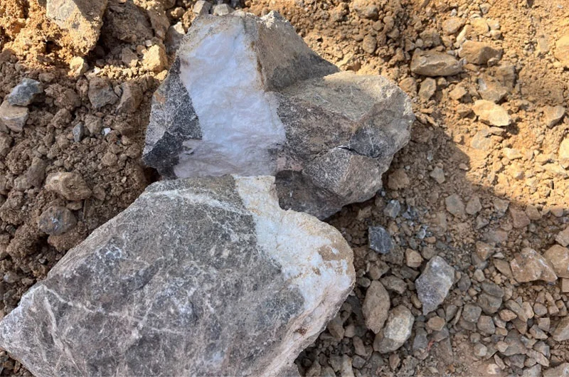
The first step in any aggregate wear parts program is to read the rock, not the crusher model. The Mohs scale — a 1 to 10 scratch-hardness ranking (Mohs scale of mineral hardness (Wikipedia)) — puts granite at 6 to 7 and limestone’s calcite at about 3; basalt sits in the same 6 to 7 band on typical industry benchmarks but combines high hardness with high impact load.

Read the table below against the rock on the belt, not the rock named on the lease:

Rock Mohs Compressive Strength Silica (SiO₂) Abrasion Index (Ai) Dominant Wear Mode
Granite 6 to 7 100 to 250 MPa 25 to 35% 0.3 to 0.5 Sliding abrasion + impact
Basalt 6 to 7 100 to 300 MPa 25 to 35% 0.3 to 0.5 Abrasion + heavy impact
Limestone / Dolomite ~3 30 to 250 MPa 2 to 10% 0.05 to 0.2 Impact (low abrasion)
River gravel 7 (quartz) 100 to 250 MPa 30 to 40%+ 0.4 to 0.6 Extreme sliding abrasion
Recycled concrete 3 to 6 (mixed) variable variable variable Abrasion + tramp metal

The figures below reflect typical industry benchmarks and the Bond Abrasion framework. Above roughly 10 to 15% silica (a commonly cited threshold), abrasion, not impact, becomes the wear driver, so a manganese part for limestone can collapse on granite and a high-chrome part for granite can crack on recycled concrete.
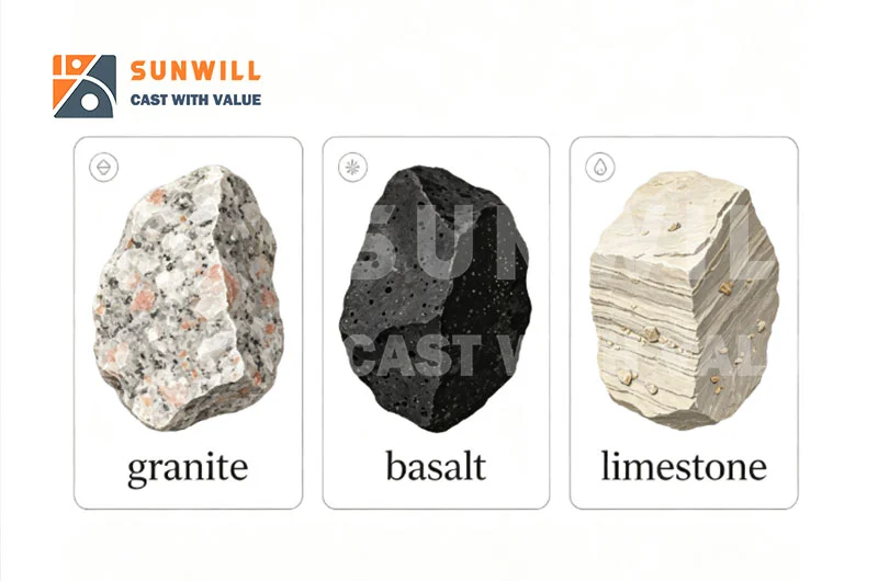
aggregate wear parts selection by rock type granite basalt limestone hardness and abrasion index

aggregate wear parts selection by rock type granite basalt limestone hardness and abrasion index

Two mistakes dominate this step: naming the deposit by its headline mineral and ignoring a contaminant (a “limestone” quarry with a granite stringer runs harder than its name), and assuming compressive strength alone sets the part. Read the rock as it actually arrives, worst week included.


Granite & Basalt Strategy: Wear Parts for Granite and Basalt

Hard rock is an abrasion problem first. Granite and basalt run 25 to 35% silica and an Abrasion Index of 0.3 to 0.5, so the winning wear parts for granite and basalt are the hardest metals that survive the feed — high-chrome blow bars (58 to 64 HRC) or ceramic/TiC-inserted blow bars pushing life to 3 to 5× a plain bar for impactors. On the cones, run high-chrome or MMC liners in tertiary duty; for jaws, Mn18Cr2 with a corrugation profile.

Metso’s impactor guidance notes HSI crushers use “different grades of steel and cast iron for the active wear parts,” and durable wear parts cut operating cost in aggregate duty (Metso Nordberg NP Series impact crushers). The rule: run high chrome or ceramic composite on clean granite and basalt, never plain high chrome where tramp can appear.

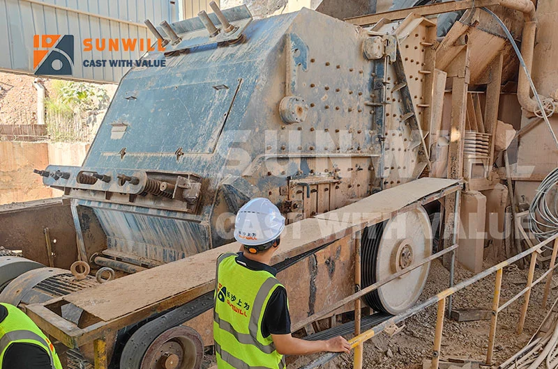
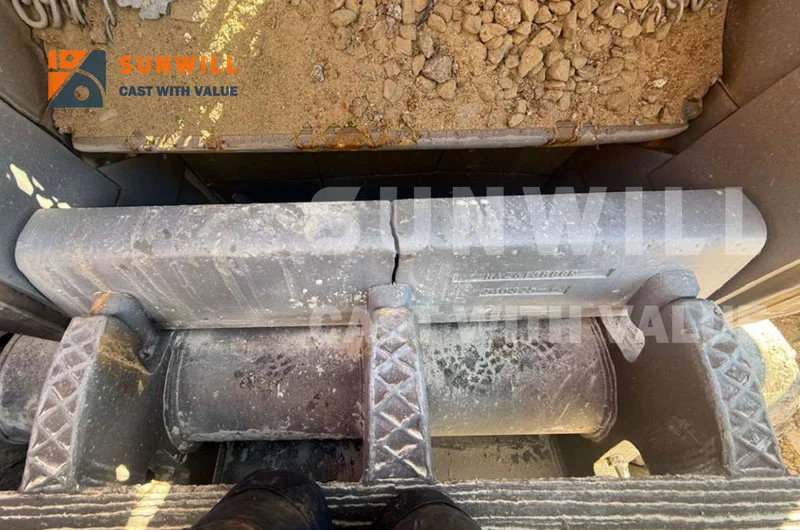
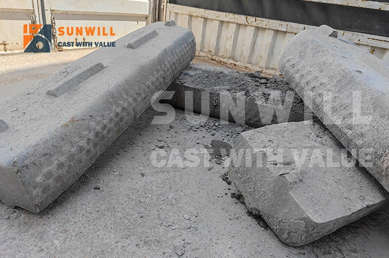
Field case — a granite quarry in Shandong, China. A 320 t/h granite operation in Shandong ran martensitic blow bars on a 1,400 mm rotor impactor at roughly 1,450 RPM, wearing out in about 2,100 operating hours and forcing six change-outs a year. Sunwill’s review recommended switching to ceramic-inserted MMC blow bars, because the ceramic carries the abrasion granite demands while the martensitic matrix absorbs the occasional shock. Set life rose to about 6,300 hours (roughly 3×), and the plant cut change-outs from six per year to two, dropping cost per ton by about 38% [CLIENT VERIFY: Sunwill project file]. The takeaway: on hard, clean rock, the composite route is where the cost-per-ton gains live. For the alloy detail, see our ceramic-inserted blow bars for hard rock guide and the blow bar material selection guide.
wear parts for granite and basalt impactor blow bars and cone liners in hard rock crushing

wear parts for granite and basalt impactor blow bars and cone liners in hard rock crushing

For basalt, the impact load runs higher than granite’s because the rock is denser and feeds in larger pieces, so lean toward manganese-based or martensitic composites in primary zones and reserve pure high-chrome for clean secondary and tertiary circuits.


Limestone & Soft Rock: Limestone Crusher Wear Parts

Soft rock flips the logic. Limestone and dolomite run Mohs ~3, silica 2 to 10%, and Ai just 0.05 to 0.2; impact is the real threat in primary crushing. The correct limestone crusher wear parts are high-manganese steels (Mn14Cr2, Mn18Cr2, Mn22Cr2) that arrive soft at 200 to 240 HB and work-harden under impact to 500+ HB while the core stays ductile. Manganese fits high-impact, variable feed: primary jaw plates, gyratory mantles and concaves, primary cone liners. But watch glazing: in low-impact secondary duty the surface never hardens and wears fast, so martensitic or medium-chrome usually wins there on cost per ton.

One nuance: “limestone” spans 30 to 250 MPa compressive strength, and the harder end with a silica stringer behaves like mild hard-rock and may justify a martensitic or composite step-up. Match the grade to measured pit strength.


Variable Aggregate: How to Choose Quarry Wear Parts for Mixed Feed

Few plants crush one rock forever, and mixed feed is the norm for most aggregate wear parts buyers. A typical quarry crusher wear parts challenge is feed mixing granite and limestone, or virgin rock with recycled concrete, and no single alloy is safe — high chrome cracks on tramp steel, plain manganese wears on granite abrasion. The balanced answer is martensitic steel (48 to 54 HRC) with ceramic or TiC inserts (MMC) — the matrix tolerates impact and contamination while the inserts carry the granite-day abrasion, which is the heart of how to choose quarry wear parts for unpredictable feed:

  • Granite + limestone blend: martensitic + ceramic blow bars and MMC cone liners; manganese only in the primary impact zone.
  • Recycled concrete + virgin rock: martensitic + ceramic, never plain high chrome; require functioning magnetic separation and metal detection.
  • River gravel + basalt: treat as hard-rock abrasion (Ai 0.4 to 0.6); high chrome or ceramic composite on clean feed, MMC where contamination risk exists.

MMC and TiC inserts require functioning magnetic separation and metal detection, because the inserts (1,600 to 3,200 HV) are brittle under point-load impact, so an undetected rebar shatters them, and composites pay off only on clean feed. A short wear study settles mixed-feed arguments: plot ultrasonic thickness against tons processed to see whether the plant is abrasion-limited (hardness up) or impact-limited (toughness up); for impactors, our Impactor Blow Bars range covers martensitic, high-chrome, and ceramic grades.


Component-by-Component: Aggregate Crusher Liner Selection

The material changes with the component, each stage a different wear mode. This is the practical aggregate crusher liner selection map: assign the alloy to the stage, not to the plant. Every aggregate wear parts buyer should treat the liner, not the whole plant, as the unit of specification.

Jaw Plates (Fixed and Moving)

Primary jaw duty is high-impact, variable feed, so Mn18Cr2 with a corrugated or tooth profile is the standard; it work-hardens under the big rocks, and the primary station wants manganese for tramp tolerance.

Cone Crusher Liners (Mantle + Concave)

Secondary and tertiary cones see high sliding abrasion at controlled impact. On clean granite and basalt, high-chrome or MMC cone liners deliver 2 to 4× the life of mono-alloys; on abrasive ore with tramp risk, Mn18Cr2 with TiC inserts in the lower band keeps impact tolerance while lifting life ~1.5 to 2×. On limestone, plain Mn18Cr2 is optimal.

Impactor Blow Bars

High chrome or ceramic MMC for clean hard rock; martensitic + ceramic for mixed and recycled feed; manganese only where rebar and tramp dominate. The blow bar selection guide carries the full table, and our Impactor Blow Bars page lists grades by model.

Chute and Hopper Liner Plates

Transfer points see sliding abrasion rather than impact, so a chromium-carbide bimetallic plate, up to 12 to 20× mild steel, is the answer; our bimetallic wear plates for chutes guide maps overlay thickness to abrasion severity.
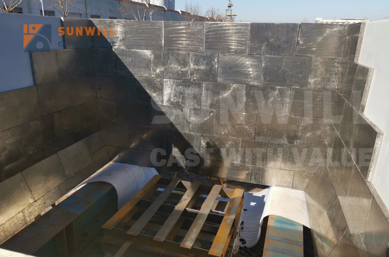
Field case — a basalt aggregate plant in central Vietnam. A 400 t/h basalt operation in central Vietnam ran plain Mn18Cr2 cone liners in its secondary and tertiary cones (basalt Ai ≈ 0.4). In the tertiary circuit the impact was low, so the manganese glazed instead of hardening and wore in about 480 hours. Sunwill recommended a 3-zone graded mantle — Mn18Cr2 core with TiC inserts in the lower and nib wear zones. Mantle life rose to about 860 hours (roughly 1.8× [CLIENT VERIFY: Sunwill project file]) and cone change-outs fell from nine per year to five.

For grinding and milling duty, our grinding roller and mill liners guide covers table and roller design where flat plate gives way to engineered cast shapes.


Selection Cheat Sheet: Aggregate Crusher Liner Selection at a Glance

When the pit report is in hand, this table is the fastest way to spec the plant — the condensed aggregate crusher liner selection reference for your aggregate wear parts planning.

Rock / Feed Primary Secondary Cone Impactor Blow Bars Chute / Hopper Life Lever
Granite (clean) Mn18Cr2 High-chrome / MMC High-chrome / Ceramic MMC Bimetallic 8+6 2 to 4× composites
Basalt (clean) Mn18Cr2 + TiC MMC cone High-chrome / Ceramic MMC Bimetallic 10+8 1.5 to 2× TiC
Limestone (clean) Mn18Cr2 Mn18Cr2 Martensitic / Medium-chrome Bimetallic 6+4 Work-hardening
Granite + limestone Mn18Cr2 Martensitic + ceramic Martensitic + ceramic (MMC) Bimetallic 8+6 Balanced
River gravel Mn18Cr2 High-chrome / MMC High-chrome + ceramic Bimetallic 10+8 Extreme abrasion
Recycled concrete Mn18Cr2 / Mn22Cr2 Martensitic + ceramic Martensitic + ceramic (MMC) Bimetallic 8+6 Tramp first

Two rules sit above the table. Never run plain high chrome where tramp steel can appear. At ~10 J/cm² it shatters on a rebar hit, so buy on cost per ton, not unit price. For the science behind each row, the blow bar material selection guide and our aggregate and quarry wear solutions overview cover the same logic by plant type.
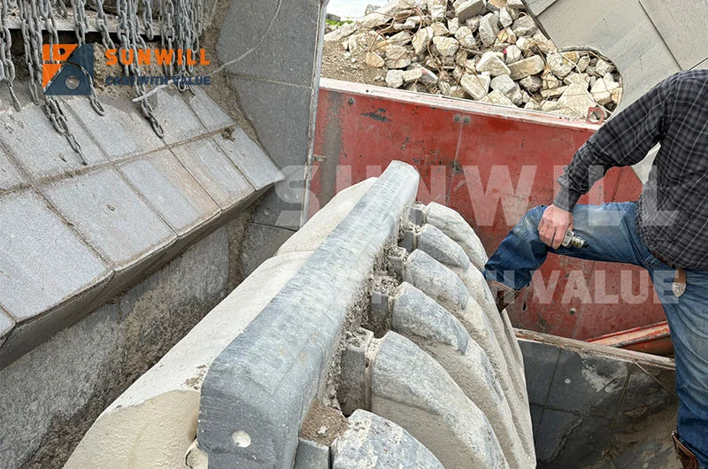
Sunwill engineering note. Sunwill is one of the few foundries in China with in-house MMC, Bimetallic, and DHT composite technologies built over two decades. The 3-zone graded structure from the Vietnamese basalt case, a tough manganese core, a work-hardening surface, and hard inserts in the high-wear zone, is the same logic behind our ceramic-inserted blow bars and ULTI 700+ bimetallic lining system. For transfer points, the bimetallic wear plates for chutes guide shows that same thinking as a flat, weldable liner, and the structures are described on our composite (MMC / Bimetallic / DHT) technologies page.


Avoid the Lowest-Price Trap: Quarry Crusher Wear Parts and Cost per Ton

The mistake costing plants most is buying quarry crusher wear parts on sticker price. BDI Wear Parts ranks downtime by operation. A medium quarry (300 tph) loses $2,000–$5,000 per hour. A large quarry (600 tph premium aggregate) loses $5,000–$10,000 per hour. High-value copper, gold, or diamond operations lose $15,000–$50,000+ per hour (BDI Wear Parts, crusher downtime reduction strategies). One unplanned change-out can erase a cheaper part’s saving many times over.
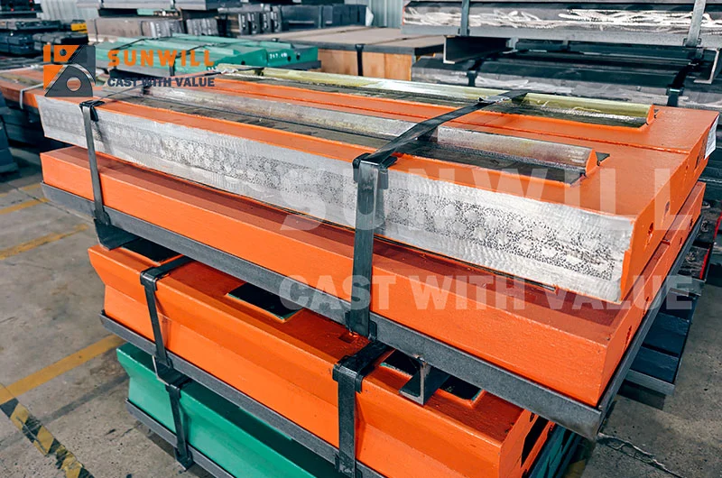
quarry crusher wear parts cost per ton comparison chart high chrome vs ceramic composite

Worked example, 320 t/h granite circuit (illustrative pricing, not a quote):
Plain high-chrome blow bar: $900, ~2,200 operating hours → ~700,000 tons (one tramp event can end it early).
Martensitic + ceramic (MMC) blow bar: $1,800 (2× the price), ~6,300 hours → ~2,000,000 tons, far lower fracture risk.

The ceramic bar is 2× the price for ~2.9× the life — cheaper per ton before downtime. A change-out typically ties up the crusher 4 to 8 hours (field estimates), at $2,000–$5,000 per hour (BDI Wear Parts); cutting six change-outs to two removes 16 to 32 stoppage hours, which is the framework behind every aggregate wear parts decision:

Cost per ton = (Part cost + Downtime cost + Labor cost) ÷ Tons produced

This same ratio drives our mining wear parts solutions guide for gyratory and cone liners. Compute it, and the “expensive” part usually wins.


FAQ

What blow bar works best for river gravel and other highly abrasive aggregate?

River gravel is dominated by quartz at Mohs 7 with 30 to 40%+ silica and a Bond Abrasion Index around 0.4 to 0.6, an extreme-abrasion duty. On clean, magnetically separated feed, high-chrome blow bars (58 to 64 HRC) or ceramic/TiC-inserted MMC blow bars deliver the longest life — ceramic composites typically run 3 to 5× a plain bar. The precondition is functioning metal detection and magnetic separation upstream, because the inserts are brittle under a point-load tramp hit. If the feed carries any rebar or tramp steel, step down to martensitic + ceramic (MMC), which keeps most of the abrasion resistance while surviving the contamination pure high-chrome cannot.

Is Mn14 or Mn18 the better choice for limestone crusher wear parts?

For most limestone primary duty, Mn18Cr2 is the safer, longer-lasting choice over Mn14Cr2. Both arrive soft at 200 to 240 HB and work-harden under impact, but Mn18Cr2 carries more manganese and chromium, hardening to a deeper, more wear-resistant surface (500+ HB) and resisting the heavier impact of large, variable feed. Mn14Cr2 stays a valid, lower-cost option for light-duty secondary positions with small, clean, low-impact feed. The deciding factor is impact energy: bigger feed and higher impact favor Mn18Cr2; gentle, clean secondary duty can justify Mn14Cr2 on price. Either way, keep manganese out of low-impact tertiary positions where it glazes.

How do you choose quarry wear parts when the feed mixes granite, limestone, and recycled concrete?

Mixed and recycled aggregate is an impact-plus-abrasion problem, so the answer is a balanced, contamination-tolerant alloy rather than a maximum-hardness one. Martensitic steel (48 to 54 HRC) with ceramic or TiC inserts (MMC) is the standard call for blow bars and cone liners: the martensitic matrix absorbs tramp hits from recycled concrete while the inserts carry the granite-day abrasion. Reserve plain high-chrome for the clean secondary and tertiary circuits only, and require functioning magnetic separation and metal detection before any composite is specified. A one-campaign wear study, ultrasonic thickness mapped against tons processed, settles whether the plant is abrasion-limited or impact-limited.


Conclusion

The cheapest aggregate wear parts are rarely the cheapest aggregate wear parts. The right aggregate wear parts decision weighs the rock against the component: high-chrome and ceramic composites for granite, basalt, and river gravel where abrasion rules; high-manganese steel for limestone and soft rock where impact rules; and martensitic + ceramic MMC for the mixed and recycled feeds that punish any single alloy. Silica above roughly 10 to 15% (a commonly cited field threshold) flips the plant from impact-limited to abrasion-limited, and the cost-per-ton framework — (part + downtime + labor) ÷ tons — justifies every upgrade to procurement.
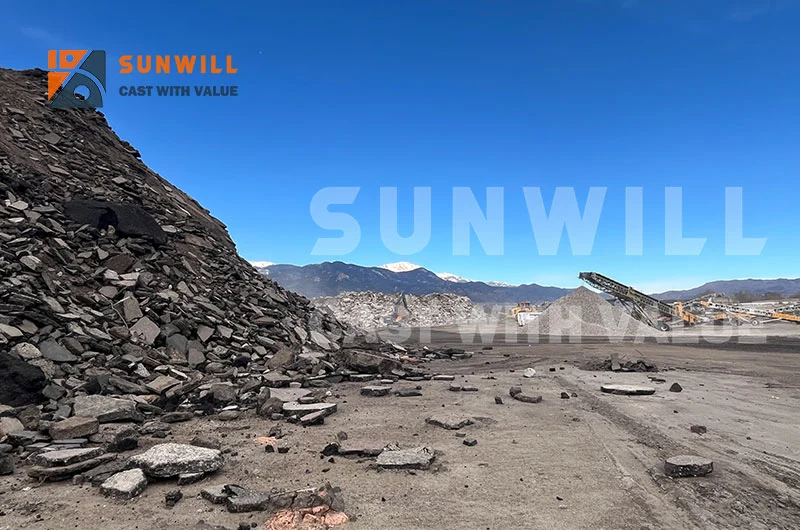
Best-in-class plants read the rock as it arrives and let measured wear, not the catalog price, set the specification.

Ready to specify the right parts for your quarry?

Sunwill’s engineering team, metallurgists and foundry engineers with 20+ years in wear-resistant materials, can run a personalized aggregate wear parts analysis against your rock chemistry, crusher model, and contamination profile. We are an ISO 9001:2015 foundry with 15,000㎡ of production space, 8,000 t of annual capacity, and parts shipped to 40+ countries, covering high-chrome, martensitic, manganese, and our proprietary MMC / Bimetallic / DHT composites.

Contact our technical team for a personalized aggregate wear-parts analysis and a free selection sheet built for your specific circuit. To see how our composite technologies are built, review our composite (MMC / Bimetallic / DHT) technologies, or browse our full range of aggregate and quarry wear solutions.
 

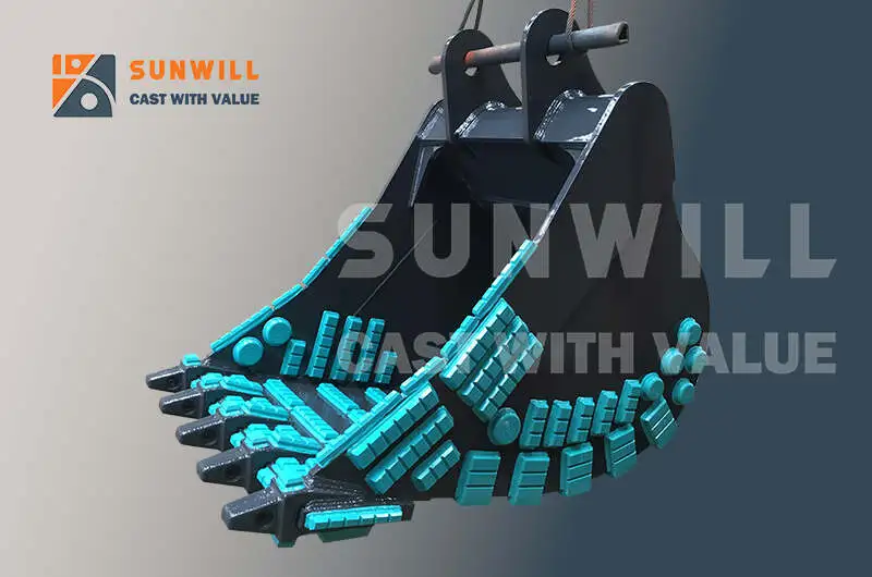
Chocky Bars and Wear Bars for Excavators, Loaders and Hoppers

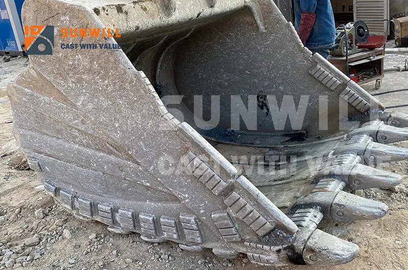
The cheapest ton you will ever save is the one that never grinds a hole in your bucket. Every shift, an excavator lip drags through abrasive rock, a loader bucket scoops the stockpile, and a hopper wall takes the full drop of the next truckload. Unprotected, those surfaces shed steel week after week until someone welds a plate over the damage and hopes. Buyers who search for chocky bars wear bars are looking for the alternative: hard, formable, weld-on protection that takes the abuse instead of the parent steel. SUNWILL is an ISO 9001:2015 certified Chinese foundry producing wear-resistant castings for cement, aggregate, mining and recycling operations, and our promise on every handling-wear package is the same: CAST WITH VALUE.

This guide covers what chocky bars actually are, how they differ from wear bars and wear liners, where to place them based on your real wear pattern, how to weld them without ruining them, and how they compare with bimetallic wear plates and hardfacing.

Key takeaway: Chocky bars work because they separate two jobs that no single material does well. A hard chromium white iron face resists abrasion, while a weldable mild steel backing carries the attachment. That duplex construction is what lets you fix cast-hardness wear resistance onto a curved bucket lip that no plate could follow.

What Are Chocky Bars?

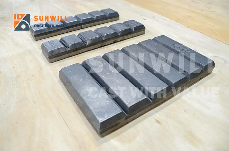
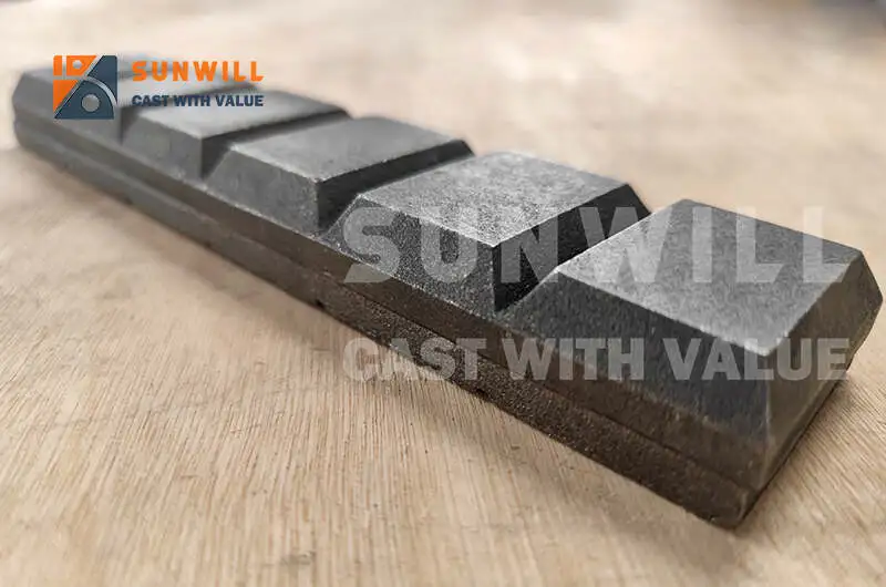
A chocky bar is a duplex wear element: a hard cast white iron wear face metallurgically bonded to, or cast onto, a weldable mild steel backing strip. Some designs are cast as segmented blocks along a continuous steel backing; others are individual blocks. The name comes from the segmented, chocolate-bar appearance of the notched versions.

The engineering problem it solves is fundamental. Chromium white iron is extremely hard and abrasion resistant, but it cannot be welded, it cannot be bent, and it is brittle. Mild steel welds beautifully and bends easily but wears away fast. Bolting the two functions together in one part gives you a wear face you could not otherwise attach and a fixing method that does not compromise the wear face.

The Notched, Formable Design

The critical feature is the notch or segment pattern across the bar. Because the hard wear face is divided into discrete blocks with the flexible steel backing running beneath, the bar can be bent to follow a curved surface. The hard segments do not bend; the backing does, and the gaps between segments open or close to accommodate the curve.

This is what makes chocky bars uniquely suited to buckets. A bucket lip and its side wings are compound curved surfaces, and a flat wear plate simply cannot follow them without extensive cutting and fitting. A notched chocky bar can be cold-formed to the contour on site.

The same notching allows cutting to length at the segment gaps, so a standard bar can be adapted to fit an irregular area without special ordering.

Typical Hardness and Construction

Chocky bar wear faces are generally cast in chromium white iron, with published hardness figures in the region of 700 HB or approximately 63 HRC depending on the grade and supplier.

Two clarifications on our own scope, because buyers deserve precision on this. Chocky bar wear faces are chromium white irons, which we cast. Ni-Hard nickel-chromium white iron to ASTM A532 is not a SUNWILL cast stock line; where a complete wear solution genuinely requires it, we specify the correct grade and source it as part of the package, and the properties are described in Ni-Hard white iron wear parts. Separately, tungsten carbide composite and hardsurfacing consumables appear in this article as market comparison only. SUNWILL does not manufacture WC composites.

Chocky Bars, Wear Bars and Wear Liners: One Family, Three Formats

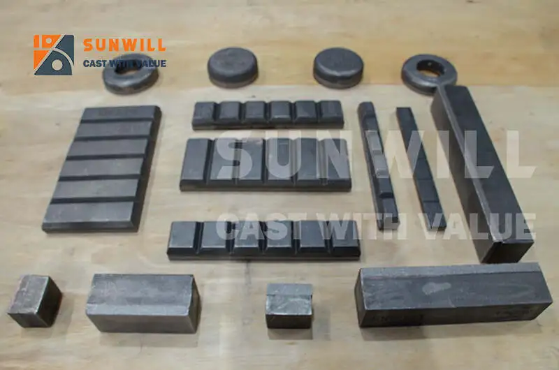
The chocky bars wear bars category covers several related formats, and choosing the wrong format is more common than choosing the wrong material.

Chocky bars and chocky blocks are the notched, formable option. Best where the surface is curved, where the wear pattern is uneven, and where you want to place protection selectively rather than cover an entire area. They are also the most impact-tolerant of the three because the segmentation limits crack propagation across the wear face.

Wear bars are longer, often continuous or lightly segmented bars intended for straighter runs: bucket lips, loader edges, chute rails and hopper edges. They provide a more continuous wear surface with fewer gaps, which suits sliding-abrasion duty where material flows along the surface rather than impacting it.

Wear liners and wear plates cover area rather than lines. Flat or gently curved surfaces such as hopper walls, chute floors and truck body panels are better served by plate products. This is where our bimetallic wear plates for chutes and hoppers belong, and the comparison against cast alternatives is worked through in overlay plate versus castings.

The right combination on a single machine usually involves all three. A loader bucket might carry heavy chocky bars on the corners and wings where gouging concentrates, wear bars along the straight sections of the lip, and a plate liner in the bucket floor where material slides.

Wear Zone Placement: Where to Put Them and Where Not To

Placement is the part most operations get wrong, and it wastes more money than material selection ever does. A chocky bars wear bars layout should be drawn from evidence, not from a catalogue diagram.

Map the Wear First

The instinct is to cover everything. Resist it. Full coverage is expensive, adds significant weight to a bucket, and is usually unnecessary because wear is never uniform.

The correct method is to observe the existing wear pattern on the unprotected part. Every bucket, hopper and chute develops a characteristic wear map determined by material flow, digging technique, and geometry. Photograph it, measure remaining thickness at several points, and mark the zones where metal loss is actually occurring.

Then place protection on those zones. You will typically find that a modest fraction of the surface area accounts for most of the metal loss.

Excavator Buckets

Corners and side wings take the heaviest gouging in most digging duties. These are prime chocky bar locations because the surfaces are curved and the load is high-impact.

The area behind the teeth and adapters sees concentrated abrasion as material funnels past. Bars here protect the lip structure that carries the tooth system. Tooth and adapter selection itself is a separate subject, covered in bucket teeth wear parts.

The bucket floor and heel wear from sliding as the bucket drags and dumps. Longitudinal runs of wear bars aligned with the material flow direction work better here than transverse placement.

The back of the bucket is often over-protected. Check whether it is actually wearing before you spend on it.

Loader Buckets

Loader duty differs from excavator duty because the machine drives into a pile rather than dragging through a face.

The cutting edge and lip take the primary abrasion. The bucket floor behind the lip wears from continuous material sliding. The side cutters and corners take impact from pile penetration. The spill guard and top edge usually need less than people assume.

Hoppers, Rock Boxes and Chutes

Here the wear mechanism changes from digging to impact plus sliding flow, and placement follows the material trajectory.

The primary impact zone in a hopper, where truck-dumped material lands, takes the highest-energy blow. Rock boxes and heavy liners suit this location better than thin protection.

The flow path down the walls takes sliding abrasion, which is where continuous wear bars or plate liners perform well.

Corners, transitions and the discharge lip concentrate flow and wear faster than the flat areas. These are high-value protection points.

Chute sides and the outer radius of any turn take the load as material is deflected. The inside radius often barely wears at all.

Leave Deliberate Gaps

A counterintuitive but important point: the gaps between chocky bar segments are useful. Fine material packs into them and forms a semi-permanent bed that itself resists wear, a phenomenon sometimes described as autogenous protection. Spacing bars deliberately, rather than butting them tight, can protect the surface between them at no material cost.

Spacing also reduces weight and cost, and on a bucket, weight matters directly. Every kilogram of protection is a kilogram off your payload.

A quarry running front-end loaders had been paying a contractor to hardface their bucket lips every few weeks, and treating it as routine. When their maintenance planner finally photographed and measured the wear pattern, it turned out nearly all the loss was concentrated at the two corners and a short section behind the centre teeth. They fitted heavy chocky bars on just those zones and left the rest bare. The repair interval stretched out substantially, and they were buying a fraction of the protection they had assumed they needed. Mapping the wear was worth more than any grade upgrade.

Not sure where your wear is concentrated? Send us photographs of your worn buckets and hoppers and we will map the zones with you. Contact the SUNWILL wear team for a placement review.

Cutting, Forming and Welding: Getting the Attachment Right

More chocky bars wear bars installations fail at the weld than at the wear face. The rules are simple and they are not optional.

Never Weld the White Iron

The hard cast wear face must never be welded, arc-struck or heated directly. It is a brittle high-carbon iron; welding it will crack it, and a cracked wear face fails prematurely and unpredictably.

All welding is done on the mild steel backing only, and on the parent plate of the bucket or hopper. The backing exists precisely to give you a weldable surface.

Cutting to Length

Cut at the segment gaps, through the steel backing only, using a cutting method appropriate to the backing material. Avoid cutting through the hard segments. If your required length falls mid-segment, plan the layout to shift the cut to the nearest gap rather than forcing it.

Forming to Contour

Cold form the bar to the surface contour by bending the backing at the notches. Work progressively rather than forcing the whole bend at once, and support the bar so the load goes into the backing and not into the hard segments. Do not heat the bar to make it bend more easily; heating risks damaging both the wear face and the bond.

Welding Practice

Clean and prepare the parent surface. Remove old weld, scale, packed fines and paint from the area. A bar welded onto packed material or old cracked overlay will not stay attached.

Consider preheat. Welding onto thick, cold, high-strength parent plate, and onto backing strips, benefits from preheat to reduce cracking risk in the heat-affected zone. The appropriate preheat depends on the parent plate grade and thickness.

Use an appropriate low-hydrogen electrode or wire matched to the backing and parent materials, following a qualified procedure. This is a welding engineering decision, not a field improvisation.

Stitch weld along the backing edges rather than laying one continuous heavy bead. Stitch welding controls heat input, limits distortion of the bucket or hopper plate, and provides adequate attachment strength. Weld sequence matters: alternate along the bar rather than working end to end, to spread the heat.

Keep the weld low and out of the wear path. A tall weld bead standing proud of the surface becomes a wear target itself and will be eroded away, taking the attachment with it. Fillet welds along the backing edge should sit below the wear face profile.

Watch distortion. Excessive heat input into a bucket floor or hopper panel can distort it. Balanced sequencing and controlled stitch length prevent this.

Safety Notes

Grinding, cutting or arc-striking on chromium white iron generates hard particulate. Follow appropriate respiratory and eye protection practice, and be aware that pieces broken from a hard wear face can be sharp and can fly. Working inside hoppers and chutes brings confined-space and fall considerations that outrank any wear-parts consideration.

A maintenance supervisor at a cement plant inherited a set of hoppers where a previous crew had welded chocky bars with a single heavy continuous bead standing proud of the wear face. Within two months, the beads had eroded and half the bars had detached, several of them into the feeder below. Refitting them with stitch welds recessed below the segment height, on properly cleaned plate, produced the service life the material had always been capable of. Nothing was wrong with the bars. Everything was wrong with the weld.

Chocky Bars, Bimetallic Plate and Hardfacing Compared

Each option occupies a genuine niche, and a sound chocky bars wear bars decision means being honest about the geometry and the duty rather than about hardness figures.


Chocky bars win on curved surfaces, on selective placement, and where impact accompanies abrasion. Their segmentation tolerates impact and limits crack spread. They are quick to fit on site with normal welding equipment, and they can be replaced individually as they wear. Their limitations are the gaps in coverage and the labour involved in fitting many individual elements over a large area.

Bimetallic wear plates win on flat and gently curved area coverage. They provide continuous protection with no gaps, typically at lower cost per square metre of protected area than assembling bars, and they suit chute floors, hopper walls and liner applications. Their limitation is conformability: a plate cannot follow a compound curve, and cutting and fitting plate to an irregular shape is slow. Our detailed treatment is in bimetallic wear plates for chutes and hoppers, and the practical questions are answered in wear plate liner FAQ.

Weld overlay and hardfacing win where geometry is genuinely awkward, where the surface must be rebuilt as well as protected, and where a skilled welder and consumables are already on site. The overlay conforms to anything. Its limitations are consistency between applications, dependence on welder skill, cumulative heat input into the parent structure over repeated repairs, and the recurring labour cost. Many operations discover that the third or fourth hardfacing cycle on the same bucket costs more in total than fitting bars would have. The comparison is developed further in overlay plate versus castings.

The realistic answer for most plants is a combination. Bars on the curved, high-impact, selectively worn zones. Plate on the flat, high-flow area coverage. Overlay for repair of the awkward remainder.

Key takeaway: Choose format by geometry before you choose material by hardness. Curved and selectively worn surfaces call for chocky bars, flat high-flow areas call for bimetallic plate, and awkward rebuild work calls for overlay. Most buckets and hoppers need a combination rather than a single answer.

Selecting by Duty: Clinker, Aggregate and Scrap

Different industries load these parts differently, and a chocky bars wear bars specification should follow the duty rather than the equipment type.

Cement plant duty is abrasive but comparatively low in unpredictable impact. Clinker is hard and hot, limestone is abrasive, and the handling equipment sees consistent, repetitive loading rather than random heavy shocks. Harder wear faces perform well here because impact risk is lower. Clinker handling adds a thermal dimension, and elevated temperature at the wear surface affects material choice. The plant-wide context is in cement plant wear parts and the programme view in SUNWILL wear parts and solutions for cement plants.

Aggregate and quarry duty brings high abrasion with moderate to high impact, especially in primary hoppers taking direct truck dumps and in loader buckets penetrating blasted rock piles. Here the impact tolerance of segmented bars is a real advantage over a large monolithic hard plate. Grade selection across the aggregate line is covered in aggregate wear parts selection, with the downtime-defence view in aggregate production wear solutions.
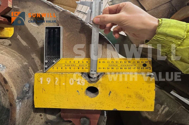
Scrap and recycling duty is the most punishing for impact. Scrap handling involves grapples, heavy irregular objects, and loads that shift and catch. This is the duty where a very hard, brittle protection choice is most likely to crack, and where segmented bars with a tough backing and generous spacing perform best. The shredder-side parts picture is in metal scrap shredder wear parts.

Sand and fines handling at the other extreme is nearly pure sliding abrasion with little impact. Here continuous coverage matters more than impact tolerance, which tends to favour plate over bars.

Total Cost of Ownership

The parts price is a poor guide, so build the comparison properly.

Protected life per fitting. How long does the protection last before it needs renewal? Divide the fitted cost, including labour, by that interval.

Fitting labour. This is often the dominant term and it is regularly ignored. A hardfacing cycle consumes skilled welder hours repeatedly. Fitting bars is a one-time labour event that lasts several times longer. Bars fitted with correct stitch welds can also be replaced individually as they wear, without redoing the whole area.

Equipment availability. A bucket in the workshop is a machine not loading trucks. Extending the interval between protection renewals directly increases machine availability, and on a busy pit that value usually exceeds the parts cost.

Parent structure preservation. The strategic term. The purpose of all of this is to stop the bucket, hopper or chute structure itself from wearing out. A bucket shell that is protected in time can run for many years; one that is allowed to wear through requires structural repair or replacement at a cost that dwarfs any protection programme.

Payload and fuel. Protection adds weight. Selective placement based on a real wear map, rather than blanket coverage, keeps that weight penalty small.

The SUNWILL CAST WITH VALUE Handling-Wear Program

Our approach to supplying chocky bars wear bars and handling-wear protection runs in four steps.

First, we map the wear. Photographs and thickness measurements of your existing worn parts, plus material, tonnage and duty details. We would rather see your worn bucket than your parts list, because the wear pattern tells us what the parts list cannot.

Second, we select format by zone. Chocky bars where geometry is curved and impact is present, wear bars on straight high-flow runs, and bimetallic or cast liners for area coverage. Selective placement, with deliberate spacing, rather than blanket coverage.

Third, we specify the grade by duty. Chromium white iron wear faces matched to the abrasion and impact balance of each zone, cast under ISO 9001:2015 with material documentation. Where a complete solution calls for grades we do not cast, including Ni-Hard, we specify and source them rather than substituting something we happen to hold.

Fourth, we support the installation. Cutting and forming guidance, welding practice notes for your welding engineer to qualify against, and a re-inspection interval so the next renewal is planned rather than discovered.

The same principles extend across the plant. Our ceramic roller liners for vertical mill work covers grinding wear, and VSI rotor shoes and anvils covers rotor shoes and anvils downstream of the same hoppers these bars protect.

CAST WITH VALUE means the protection is engineered against your fitted cost and your equipment availability, not against the lowest unit price on a quotation.

Frequently Asked Questions

What are chocky bars wear bars and how do they work?
They are weld-on wear protection elements built from two materials with different jobs. A hard chromium white iron wear face resists abrasion, and a weldable mild steel backing carries the attachment to the equipment. Chocky bars are notched into segments so the backing can be bent to follow a curved surface such as a bucket lip, and cut to length at the gaps. Wear bars are longer, less segmented versions for straighter runs. Both are welded through the backing only, never through the hard face.

Can chocky bars be welded directly on the hard wear face?
No, and this is the most important installation rule. The cast white iron face is brittle and high in carbon; welding or arc-striking on it will crack it and cause premature failure. All welding is performed on the mild steel backing and the parent plate, using a qualified procedure with appropriate electrode selection and preheat for the parent material. Keep weld beads low so they do not stand proud of the wear face and become a wear target themselves.

How do chocky bars wear bars compare to bimetallic wear plates?
They solve different geometric problems. Chocky bars conform to curves, allow selective placement on high-wear zones, and tolerate impact well because segmentation limits crack propagation. Bimetallic wear plates give continuous, gap-free coverage of flat and gently curved areas, usually at lower cost per protected square metre. Most operations use both: bars on bucket corners, lips and wings, and plate on hopper walls and chute floors.

How do I decide where to place chocky bars on a bucket?
Work from the observed wear pattern, not from a template. Photograph and measure the worn, unprotected part to find where metal is actually being lost. In most digging duties, that means corners, side wings and the area immediately behind the teeth, while the back of the bucket often wears far less than people assume. Protect the zones that are wearing, leave deliberate spacing between bars so fines can pack and provide additional protection, and keep total added weight in mind because it comes directly off your payload.

How long do chocky bars last?
Service life depends almost entirely on the abrasiveness of the material, the impact severity, the machine duty cycle and the quality of the installation, so any single figure would be misleading. The useful approach is to record the fitted date and the measured thickness at intervals on your own equipment, establish your own wear rate per zone, and set a renewal trigger from that data. Correct welding practice and selective placement typically influence achieved life more than small differences in wear-face hardness.

Conclusion

Handling wear is the least glamorous part of a wear programme and one of the most profitable to get right. The crusher gets the engineering attention, but the bucket, the hopper and the chute quietly consume welding labour, machine availability and eventually structural steel.

Specifying chocky bars wear bars properly comes down to four disciplines. Map the actual wear pattern before you buy anything. Choose the format by geometry, with bars for curves and selective zones and plate for flat area coverage. Weld through the backing only, with stitch welds kept below the wear face profile. And judge the result on fitted cost and equipment availability rather than on unit price.

Get those right and the parent structure outlives several generations of protection, which was the whole point.

Send us photographs of your worn buckets, hoppers and chutes along with your material and duty details. We will map the wear zones, propose a format and grade per zone, supply parts cast under ISO 9001:2015, and give your welding team the installation guidance to make them last.

Ready to stop rewelding the same bucket? Contact the SUNWILL wear engineering team for a wear-zone mapping review and a CAST WITH VALUE handling-wear plan.


Authoritative References

SUNWILL Blow Bar Material Grade Codes & Application Matrix

Procurement managers rarely get three identical quotes. They get three that look nothing alike. Sarah, a plant buyer for a Midwest aggregates operator, opened three supplier proposals for impact crusher blow bars last spring. One listed a competitor OEM number. The second used a raw chemistry code. The third simply said “Premium Ceramic Grade C.” Sarah had no clean way to compare them, which is exactly why a clear blow bar material grade chart matters before you ever request a quote.

That confusion costs plants real money. When suppliers speak different dialects, buyers lose leverage and crushers risk costly mismatches. This article presents the complete SUNWILL blow bar material grade reference, a single standardized system that maps every blow bar material grade to its composition, reinforcement, feed size limit and typical application. You will find all eight SUNWILL standard grades plus our customized options explained in plain language, so you can match any crushing job to the right code and request a quote vendors can actually honor.

If you arrived from our failure analysis guide or our feed size selection guide, you already know the “why.” This page is the “what to order,” the final stop where product codes meet purchasing decisions.

Key Takeaways
– One readable code system: the leading number signals the matrix (650 high chrome, 550 martensitic, 200 manganese) and the suffix signals the reinforcement (C or X ceramic, TI TiC carbide).
– Eight standard grades cover limestone, granite, basalt, asphalt, river pebble, concrete recycling and blasted limestone across feed sizes from below 300 mm to unlimited.
– Ceramic composite blow bar grades 650C and 700CX deliver the longest wear life on abrasive rock, while the 550 martensitic family accepts the largest feed and the toughest impact.
– 200MN represents the industry standard high manganese category (ASTM A128 type); SUNWILL’s manganese focus is the enhanced 200MNTI with TiC rods for superior wear life.
– Every SUNWILL grade is produced under the CAST WITH VALUE promise, and non standard sizes and matrix tweaks are available through our customized solutions program.

Skip the theory? If you already know your rock type and feed size, our blow bar selection by feed size guide maps those inputs straight to candidate grades. Or scroll to the complete matrix below.

Why a Standardized Grade Code Matters

Walk into any crusher wear parts marketplace and you meet four languages at once. Some vendors quote by OEM part number that only means something if you own that machine. Others quote raw chemistry percentages that say little about field performance. A third uses trademarked names that differ foundry to foundry. The fourth invents in house codes with no published meaning.

This chaos is expensive. When Sarah could not line up her three proposals, she risked buying the wrong bar for her feed or paying a premium for a grade she did not need. If your current bars are failing early, our guide to blow bar failure causes explains how material mismatch drives most premature wear.

SUNWILL impact crusher blow bar material codes solve this with one readable system. The first digits tell you the base matrix. The letters that follow tell you the reinforcement. A buyer who sees “650C” instantly knows the base is high chrome and the upgrade is C type ceramic. No translation required, no private dictionary to memorize.

That transparency pays off three ways: procurement compares quotes on equal terms, maintenance orders the right part without a catalog, and engineers specify metallurgy with confidence. Every SUNWILL grade behind these codes is produced under the same promise: CAST WITH VALUE. We engineer for cost per ton, not just for the lowest sticker price, and we publish what each code means so you can verify the value yourself.

The SUNWILL Blow Bar Grade Matrix (Complete Reference)

The table below is the master reference for all SUNWILL blow bar grades. Bookmark it. Every section that follows expands one row into a working profile with selection logic.

Material Code Reinforcement Blow bar applied Feed size control Typical application
High chrome 650 N/A All <300mm Limestone, granite, asphalt, basalt, river pebble crushing. Please keep us advised when crush river pebbles to adjust for better performance.
High chrome + Ceramic 650C C-type ceramic Height >60mm <300mm Limestone, granite, asphalt, basalt, river pebble crushing (river pebble requires tuning).
High chrome + Ceramic 700CX X-type ceramic Height >60mm <300mm Extremely abrasive stones e.g. high silicon rocks
Martensitic 550 N/A All <600mm Concrete recycling, limestone crushing quarry.
Martensitic + Ceramic 550MC C-type ceramic Height >60mm <600mm Concrete recycling, limestone crushing quarry.
Martensitic + Ceramic 550MC+ C-type ceramic Height >100mm <400mm Concrete recycling, limestone crushing quarry.
Manganese 200MN N/A All Not limited Blasted limestone crushing in quarry
Manganese + Tic 200MNTI Tic carbide rod Height >60mm Not limited Blasted limestone crushing in quarry

Two quick notes. “Blow bar applied” means the minimum bar height the grade is designed for. Ceramic and TiC reinforced grades need enough section height to seat the inserts, so they show a minimum height rather than “all.” “Feed size control” is the maximum recommended single feed dimension; exceed it and impact stress can exceed what the matrix tolerates. Our full material specs and composition guide explains the chemistry behind each family.

High Chrome Family: 650, 650C, 700CX

High chrome irons win on abrasion resistance and shrug off the cutting action of silica rich rock. The trade off is brittleness, so the whole family is capped at feed below 300 mm and is not recommended where large tramp iron is expected.

650 High Chrome (The Versatile Baseline)

Specs: High chrome white iron, Cr above 20 percent, above 60 HRC, no ceramic, all bar heights, feed below 300 mm.

The 650 is the workhorse of the SUNWILL high chrome line and the grade most quarries start with for secondary and tertiary HSI duty. Use it as your default when the rock is abrasive but clean and the feed is screened below 300 mm.

One warning the application note carries for good reason: when you crush river pebbles, tell us first. River pebble hardness and silica vary widely, so we tune the matrix chemistry before casting. A note in your order prevents a premature failure.

Ready to confirm your chemistry? Our blow bar material specs and composition guide breaks down the alloying strategy behind 650 and its ceramic siblings.

650C High Chrome + C-Type Ceramic (Wear-Upgraded 650)

Specs: High chrome white iron, Cr above 20 percent, above 60 HRC matrix with ceramic above 1400 HV, C type ceramic, bar height above 60 mm, feed below 300 mm.

The 650C takes the 650 matrix and embeds a C type ceramic lattice across the wear face, placing ultra hard cells exactly where abrasion bites hardest. Choose it over 650 when wear life, not first cost, controls your budget. Ceramic composite blow bar grades like 650C routinely outlast plain high chrome by multiples in abrasive service because the ceramic resists the sliding wear that eats a monometal bar. Industry wear studies report several times longer life in clean, abrasive feeds. The 650C needs a bar height above 60 mm so the ceramic structure seats correctly; if your bars are thinner, stay on 650 or ask us about a custom section.

700CX High Chrome + X-Type Ceramic (Maximum Wear)

Specs: High chrome white iron, Cr above 20 percent, above 60 HRC matrix with X type ceramic above 1400 HV, bar height above 60 mm, feed below 300 mm.

The 700CX sits at the top of the high chrome pyramid, swapping in the more aggressive X type ceramic lattice for maximum wear resistance on the most punishing rock. Reach for it when 650C still wears too fast: high silicon granite, quartz rich river gravel and other extreme abrasives are its home turf. For hard rock quarry programs specifically, our hard rock quarry blow bars resource covers feed preparation and crusher settings that protect ceramic grades. The choice between 650C and 700CX is a wear severity call: moderate duty leans 650C, rock that destroys 650C in a season leans 700CX. The 650, 700CX and 550MC blow bar configurations together cover most abrasive and mixed duty quarry work, which is why they are the three codes our sales team quotes most often.

Martensitic Family: 550, 550MC, 550MC+

Martensitic alloy steels trade some hardness for a large gain in toughness. That toughness is what lets the family accept feed up to 600 mm, far beyond the high chrome cap, and survive impact that would shatter a brittle bar.

550 Martensitic Alloy Steel (The Balanced Option)

Specs: Martensitic alloy steel, Cr above 4 percent, above 53 HRC, no ceramic, all bar heights, feed below 600 mm.

The 550 is the balanced all rounder. Notice the feed window: where high chrome stops at 300 mm, 550 runs to 600 mm because martensite absorbs impact through controlled toughness while high chrome cracks under heavy shock. If your feed is unscreened, mixed with rebar, or simply large, 550 is the safer base.

Mini story. A concrete recycling yard in the Ohio River valley was burning through a competitor’s standard martensitic bar every three weeks because rebar and oversize chunks overloaded it. SUNWILL moved them to 550MC. Changeout stretched from three weeks to roughly two months, and emergency downtime fell to near zero.

550MC Martensitic + C-Type Ceramic

Specs: Martensitic alloy steel, Cr above 4 percent, above 53 HRC matrix with ceramic above 1400 HV, C type ceramic, bar height above 60 mm, feed below 600 mm.

The 550MC adds C type ceramic to the 550 matrix, marrying martensitic toughness with ceramic wear resistance on the leading edge. This is the grade for abrasive material that still carries impact risk: recycling with light rebar, quarry limestone with occasional oversize, or any duty wanting ceramic life without high chrome brittleness. It is the most versatile ceramic grade because its matrix tolerates the largest feed of any ceramic option.

Want ceramic life with impact safety? Talk to our engineers about 550MC for your recycling or mixed feed line.

550MC+ Martensitic + C-Type Ceramic (Heavy-Duty)

Specs: Martensitic alloy steel, Cr above 4 percent, above 53 HRC matrix with ceramic above 1400 HV, C type ceramic, bar height above 100 mm, feed below 400 mm.

The 550MC+ is the heavy duty cousin, same ceramic concept as 550MC but engineered for large section bars on big machines. Because the section must exceed 100 mm, 550MC+ suits large rotor impactors where bar mass helps absorb shock. Feed is capped at 400 mm (tighter than 550MC’s 600 mm) because the heavy duty layout targets sustained large volume duty rather than occasional oversize.

Manganese Family: 200MN, 200MNTI

Manganese steel brings the ultimate in impact toughness. It work hardens under repeated impact, so its surface hardens the longer it runs while the core stays ductile. That makes it the pick for the dirtiest, most tramp laden feeds.

200MN Standard Manganese Steel

Specs: High manganese austenitic steel, Mn above 13 percent, above 250 HB as supplied (work hardens well beyond that in service), no reinforcement, all bar heights, feed not limited.

The standout property is unlimited feed size. No other family accepts uncrushable and oversize material so willingly, because each impact densifies the surface toward 500 HB plus while the core absorbs shock without cracking.

Important clarification on this code. The 200MN label denotes the general high manganese steel class used across the industry, not a SUNWILL exclusive formulation. SUNWILL’s manganese development focus is the enhanced grade below, 200MNTI, which adds TiC carbide rods for dramatically better wear life. If your operation requires standard Mn13 class manganese, SUNWILL can supply it on a project basis, but it is not the first recommendation we lead with. For most buyers we steer toward 200MNTI unless a plain manganese spec is contractually required.

200MNTI Manganese + TiC Carbide Rods (SUNWILL Signature)

Specs: High manganese austenitic steel, Mn above 13 percent, above 250 HB matrix with TiC rods above 63 HRC (roughly 2800 to 3200 HV), TiC carbide rods, bar height above 60 mm, feed not limited.

The manganese tic blow bar specification centers on the TiC rods. Titanium carbide is among the hardest engineering ceramics, measuring around 2800 to 3200 HV and above 63 HRC in rod form. The rods sit in the high wear crests and edges. As the surrounding manganese work hardens and wears preferentially, the rods protrude slightly and shield the matrix, a self reinforcing pattern that extends life well beyond plain manganese.

Why this is the SUNWILL signature. Standard high manganese wins on toughness but loses on wear rate. Plain TiC bars (or full ceramic) win on wear but can be brittle. The 200MNTI keeps the manganese matrix’s impact toughness, unlimited feed tolerance and tramp immunity, then adds a hard phase exactly where abrasion does the damage. Composite wear data shows TiC reinforced manganese blow bars running one and a half to two and a half times longer than plain manganese in matched applications.

Mini story. A primary crushing quarry in Southwest China ran blasted limestone with heavy tramp and no practical feed control. Plain high chrome shattered; plain manganese wore out in days. SUNWILL supplied 200MNTI bars tuned to the rotor. The manganese matrix shrugged off the tramp and oversize, while the TiC rods held the wear crests. The operator reported wear life several times longer than the previous plain manganese bars, with zero brittle failures. For that duty profile, 200MNTI was the only grade that satisfied both the toughness and the wear demands.

If your crushing sits in the high impact, no feed control, abrasive edge wear zone, 200MNTI is the candidate to test first.

See the TiC advantage on your next order? Request a 200MNTI quotation and tell us your crusher model and feed.

Customized Solutions Beyond Standard Grades

The eight grades above solve the large majority of jobs, but not everything. SUNWILL also offers customized solutions tailored to your need for optimal wear resistance by adjusting the matrix material or the specially designed ceramic structures.

A custom program starts with one of three triggers: an unusual feed chemistry no standard grade addresses, a crusher model with a non standard bar pocket, or field data showing a specific wear pattern (edge wear but not face wear) that a tailored ceramic layout would fix better than a stock grade.

Our engineers customize two ways. First, we adjust the matrix by shifting chromium, molybdenum or carbon to bias toward wear or toughness for your rock. Second, we redesign the ceramic structure, changing cell density, depth or placement so the hard phase sits on your highest stress zone. The result is a bar built around your operation, not a catalog average.

Mini story. A Sichuan aggregate producer crushing 100 to 300 mm high silica limestone was getting only about 80,000 tons of life from standard high chrome bars. SUNWILL engineers visited the site, analyzed the feed and impact parameters, then delivered a ceramic reinforced high chrome solution tuned to that silica profile. Service life climbed to roughly 210,000 tons per set. The upgrade was not a stock code off the shelf; it was a tailored matrix and ceramic design built from the quarry’s own data. That is the CAST WITH VALUE promise in action: we do not just sell you the nearest grade, we engineer the right one.

Have a wear problem no stock grade solves? Send us your application details and our engineers will scope a customized solution.

How to Choose Your SUNWILL Grade: Quick Selection Guide

If you have read our blow bar selection by feed size guide, you already narrowed the field by feed dimension and material. This guide is the last step: turning those inputs into a specific SUNWILL code.

Step 1. Pick the matrix family from your feed and risk profile.
– Clean, abrasive rock, screened feed below 300 mm, no tramp iron risk: choose the High Chrome family (650, 650C, 700CX).
– Mixed or large feed up to 600 mm, some rebar or oversize, impact risk present: choose the Martensitic family (550, 550MC, 550MC+).
– No feed control, heavy tramp, blasted rock, maximum toughness needed: choose the Manganese family (200MN, 200MNTI).

Step 2. Decide whether you need ceramic or TiC reinforcement.
– You want the lowest first cost and the duty is moderate: take the base grade (650, 550, or 200MN class).
– You want maximum wear life and the bar height supports inserts: add ceramic (650C, 700CX, 550MC, 550MC+) or TiC (200MNTI).
– Rule of thumb: if you change bars more than once a month, the upgrade grade almost always wins on cost per ton.

Step 3. Confirm the exact code against the constraints.
– Check blow bar height against the “applied” column. Ceramic and TiC grades need height above 60 mm (550MC+ needs above 100 mm).
– Check feed size against the “control” column. High chrome stops below 300 mm; martensitic runs larger; manganese is unlimited.
– Match the application note. River pebble on chrome? Tell us to tune. High silicon rock? Move up to 700CX.

Fast lookup. Feed controlled below 300 mm and clean? High Chrome: 700CX for extreme abrasion, 650C for max life, or 650 for value. Feed large or dirty with impact risk? Martensitic: 550MC for ceramic life with impact safety, or 550MC+ for big rotors. No feed control, tramp heavy? Manganese: 200MNTI for wear life or the 200MN class for a plain spec. Still unsure? Our engineers are who to ask.

Grade Cross-Reference (Competitive Mapping)

Buyers often arrive with a competitor or OEM code and ask what SUNWILL grade matches. The honest answer: mapping is possible, but it must be done carefully. OEM and competitor codes rarely publish full chemistry or reinforcement method. A rival “Ceramic Grade C” might mean C type or X type ceramic, in a chrome or martensitic matrix, with unknown insert density. Guessing from a name risks the wrong matrix in your crusher.

SUNWILL recommends a three input mapping. First, share the competitor code and any datasheet you have. Second, share your crusher model and bar drawing so we can confirm fit and section height. Third, share a worn bar or feed sample so we can read the actual wear mechanism. With those, our technical team maps the competitor grade to the nearest SUNWILL code, or designs a custom grade if nothing standard fits.

A few safe general mappings hold most of the time. Plain high chrome OEM bars map to 650. Chrome plus ceramic maps to 650C or 700CX depending on the ceramic type. Martensitic OEM bars map to 550, and martensitic plus ceramic to 550MC or 550MC+. Plain manganese maps to the 200MN class, while TiC enhanced manganese maps to 200MNTI. These are starting points, not final specs.

When tramp iron or odd wear shows up, also review our impact crusher wear troubleshooting guide to separate material mismatch from machine setting problems before you switch grades.

Conclusion: Pick the Code, Then Let Us Engineer It

SUNWILL blow bar grades exist to remove the guesswork Sarah faced at the top of this page. One code system, seven standard grades plus a specialized manganese option, and a customization program. The matrix tells you the base, the suffix tells you the reinforcement, and the application note tells you the job.

The conversion endpoint of this series is simple. You learned why bars fail, how feed size gates your choices, and what each material is made of. Now you know the exact codes to order, whether that is a 650C for abrasive limestone, a 550MC for recycling with rebar, or a 200MNTI for tramp heavy primary duty.

Send us four things and we will return a professional grade recommendation, not a generic catalog page:
1. Your material (rock type, silica content if known)
2. Your feed size (max dimension and whether it is controlled)
3. Your crusher model (OEM and model, or the bar drawing)
4. Your current failure problem (short life, breakage, edge wear, or unknown)

Email those details to our team or use the form at SUNWILL Contact. We will map your job to the right SUNWILL code, confirm bar fit, and quote with the CAST WITH VALUE engineering behind every grade. When your next blow bar changeout comes, make it the one where you ordered by code instead of by hope.

Ready to order by code? Send your four point spec to SUNWILL and get a graded recommendation this week.

For hands on guidance during the swap, our blow bar replacement procedure guide walks through safe installation so you protect your new grade from day one.

impact crusher side liner wear## Standards and Authoritative References

OEM vs aftermarket wear parts

Frequently Asked Questions

How do I choose between 650 and 650C?
Pick 650 when feed is clean and abrasive but cost sensitive, and you change bars on a predictable schedule. Pick 650C when wear life drives your budget and the bar height exceeds 60 mm. The ceramic cells in 650C resist sliding abrasion far better than plain chrome, so 650C typically lasts several times longer in abrasive service even though it costs more up front. If 650C still wears too fast on very high silica rock, move to 700CX.

What is the difference between 200MN and 200MNTI?
200MN represents the industry standard high manganese steel class (Hadfield type, ASTM A128 style), with Mn above 13 percent and unlimited feed tolerance. 200MNTI is SUNWILL’s enhanced manganese with TiC carbide rods embedded in the wear zone. Both keep manganese’s impact toughness and unlimited feed, but 200MNTI adds a hard phase that extends wear life one and a half to two and a half times beyond plain manganese in matched applications. SUNWILL leads with 200MNTI for most manganese duty; the 200MN class is supplied on a project basis when a plain spec is required.

Will the ceramic inserts fall out or break off?
No, not in correct application. The ceramic cells are cast into the molten matrix during pouring, so they are metallurgically bonded rather than glued or mechanically trapped. The matrix absorbs impact while the ceramic carries the wear. Failure risk rises only when the grade is misapplied, for example putting a high chrome ceramic bar in feed with large tramp iron. That is why we cap high chrome ceramics at feed below 300 mm and steer tramp heavy duty to the martensitic or manganese families.

Can you make non standard sizes?
Yes. Beyond the seven standard grades, SUNWILL offers customized solutions that adjust matrix composition or ceramic structure for specific applications. Non standard bar pockets, unusual crusher models, and tailored ceramic layouts are all within scope. Send your drawing or crusher model and our engineers will scope it.

What feed size can each SUNWILL grade handle?
High chrome grades (650, 650C, 700CX) are capped below 300 mm feed. Martensitic grades run larger: 550 and 550MC below 600 mm, 550MC+ below 400 mm. Manganese grades (200MN, 200MNTI) accept unlimited feed because the matrix tolerates oversize and tramp. Always match the “feed size control” column in the matrix to your real feed, not your ideal feed.

How do I map a competitor or OEM code to a SUNWILL grade?
Share the competitor code and any datasheet, your crusher model or bar drawing, and a worn bar or feed sample. Our technical team maps it to the nearest SUNWILL code or designs a custom grade. Plain high chrome maps to 650, chrome plus ceramic to 650C or 700CX, martensitic to 550 or 550MC, and TiC manganese to 200MNTI. Treat these as starting points until confirmed against real specs.

Blow Bar Material Technical Specifications: Composition, Hardness & Performance Trade-offs

David Chen stared at two supplier quotes on his screen and felt the familiar headache return. Both described blow bar material specifications for his limestone quarry, yet the numbers spoke two different languages. Supplier A promised a blow bar rated at 62 HRC. Supplier B quoted 350 HB. Same crusher, same feed, wildly different numbers. Which bar was actually harder, and which would survive longer in his plant? David is not alone. Most crushing engineers have faced this wall of incompatible hardness scales, and the confusion quietly drives expensive purchasing mistakes. This article is the unified reference you have been missing. We lay out the six major blow bar materials with their exact composition and hardness values, explain why HRC, HB and HV are not interchangeable, and show you how to read the wear versus impact trade-off that decides real world performance.

You run an impact crusher and need a blow bar that does not shatter on the first boulder yet does not erode by lunchtime. We agree that sorting through Cr percentages, carbide types and hardness scales feels like decoding a foreign standard. Here is our promise: by the end of this page you will hold an accurate spec sheet to send any supplier plus a clear framework for matching material to duty. We preview the six material families, the hardness scale logic, a visual wear impact map, an application matrix, a cost per ton model and the ceramic and TiC technologies reshaping the category.

Key Takeaways
– High chrome irons deliver the highest matrix hardness at greater than 60 HRC but rank lowest on impact toughness, so they suit low to medium shock duty only.
– Ceramic reinforcement (ZTA honeycomb or TiC rods) lifts wear life roughly 2 to 4 times versus the base alloy without lowering the matrix impact resistance.
– No single material wins every job; the right choice is the one that balances abrasion resistance and impact toughness for your specific feed.
– Manganese steel starts soft at greater than 250 HB but work hardens toward 450 to 500 HB under impact, which is why it fails fast when the load never shocks it.
– Ceramic and TiC composite bars cost more up front yet lower cost per ton through fewer change outs and less downtime, the core idea behind SUNWILL’s CAST WITH VALUE promise.

Understanding Hardness Scales: HRC vs HB vs HV

Before comparing any blow bar material composition HRC value against a Brinell or Vickers number, you need to know why the industry uses three different rulers. None of them is “wrong”. They simply measure different things, and mixing them without context is how good engineers buy the wrong bar.

Why different materials use different scales

The Rockwell C (HRC) scale drives a diamond cone into the surface under a major load and reads the penetration depth. It works best on hard, shallow materials, which is exactly why high chrome and martensitic bars are quoted in HRC. The Brinell (HB) scale presses a hardened steel ball into the part and measures the width of the impression. It averages over a larger area, so it suits ductile, work hardening metals like manganese steel where a localized Rockwell reading would mislead. The Vickers (HV) scale uses a diamond pyramid and works across the full hardness range, which makes it the only practical tool for ceramic phases that sit far above the HRC ceiling.

A ceramic insert at 1400 HV simply cannot be expressed on the Rockwell C scale because the cone would shatter before registering a number. That is a measurement boundary, not a material weakness.

A rough conversion you can use in the field

Treat the table below as a directional guide only. Hardness conversion is not a precise math function because it depends on the material’s modulus, carbide volume and heat treatment. Never quote these as exact equivalents on a purchase order.

Observable reading Rough HRC band Rough HB band Where you see it
Ceramic phase Above scale Above scale 1400 to 1700 HV (ZTA)
High chrome matrix 60+ 650 to 700+ High chrome, high chrome ceramic
Martensitic matrix 53 to 58 530 to 620 Martensitic, martensitic ceramic
Manganese as cast 25 to 30 (approx) 250 (as cast) Manganese, manganese TiC
Manganese work hardened 45 to 50 (approx) 450 to 500 Surface after impact

Notice the trap. Manganese at 250 HB looks dramatically “softer” than high chrome at 60 HRC, yet in service the manganese surface can rival the chrome in hard contact zones. The static number is not the whole story.

The beginner mistake: “higher HRC is always better”

The single most expensive assumption in crusher wear parts is that the biggest hardness number wins. It does not. Hardness and toughness pull in opposite directions. Push matrix hardness too high and you get a bar that resists abrasion beautifully but snaps on the first oversize rock or piece of tramp steel. High chrome at 62 HRC is brilliant in steady, low shock grinding and fragile under a 500 mm boulder. Manganese at 250 HB shrugs off that same boulder because it deforms instead of cracking. The goal is never maximum hardness. The goal is the right balance for the duty, which is the theme of this entire article.

A quick note for specifiers: SUNWILL can specify and source Ni-Hard grades to ASTM A532 (a nickel chromium white iron family) for projects that require them, but these are not held as standard stock. Tungsten carbide (WC) overlay and hardfaced bars are mentioned here only as a comparison baseline, not as a SUNWILL production line.

The Six Major Blow Bar Material Categories

Every blow bar on the market traces back to one of six material architectures. Two are base alloys, two add ceramic honeycomb reinforcement, and two build on manganese steel with either plain chemistry or TiC carbide rods. The table below is the spine of this article. Save it, print it, and send it to suppliers so everyone quotes on the same vocabulary.

Blow bar Material Main Composition Hardness
High Chrome Cr >20%, C >2.8%, Mo/Ni alloy Matrix >60 HRC
High Chrome + Ceramic Chrome base + ZTA ceramic honeycomb Matrix >60 HRC / Ceramic >1400 HV
Martensitic Cr >4%, C >3.5%, Mo/Ni alloy Matrix >53 HRC
Martensitic + Ceramic Martensitic base + ZTA ceramic honeycomb Matrix >53 HRC / Ceramic >1400 HV
Manganese Mn >13%, C >1% >250 HB
Manganese + TiC Manganese base + TiC carbide rods Matrix >250 HB / TiC >63 HRC

1. High Chrome (High Chromium White Iron)

High chrome blow bars are cast from a white iron with Cr above 20 percent, C above 2.8 percent, and molybdenum and nickel as the key alloying elements. The high chromium content drives the formation of chromium rich M7C3 carbides inside the matrix. Those carbides are themselves extremely hard, often testing 1200 to 1500 HV, and they form a continuous skeleton that carries the abrasion load.

The measured matrix hardness sits at greater than 60 HRC, which places high chrome at the top of the wear resistance ladder. A typical 20 to 26 percent chrome grade reaches 58 to 64 HRC with impact toughness around 10 J/cm2, a low number that tells you everything about its weakness.

The microstructure is the story. A network of hard M7C3 carbides sits in a martensitic or austenitic matrix. The carbide skeleton fights wear. The matrix holds it together and absorbs what shock it can. The advantage is clear: in steady, low to medium impact duty, high chrome outwears almost everything else per dollar of purchase price.

The disadvantage is brittleness. Low impact toughness means a single oversize feed lump, a piece of tramp steel, or a frozen bearing can crack the bar. High chrome is a fine crushing and medium duty material, not a primary crusher boulder tamer.

Mini story: the granite mistake. Mike Olsen ran a granite aggregate plant in the Pacific Northwest and, chasing the highest hardness number on paper, specified high chrome bars for a primary horizontal shaft impactor. The feed included 400 to 600 mm boulders from the face. Within nine days he lost three bars to transverse cracking. The supplier had quoted 62 HRC, but the impact energy exceeded what that matrix could absorb. Mike’s failure is documented in our blow bar failure causes guide, and it is the textbook case of hardness chosen without the impact side of the equation. Switching to a martensitic grade stopped the breakage while a ceramic composite was trialed for wear life.

Typical applications: limestone fine and medium crushing, cement clinker, coal, and any low shock abrasive duty where feed is screened and tramp free.

2. High Chrome + Ceramic Composite

Take the high chrome bar above and embed a ZTA (zirconia toughened alumina) ceramic honeycomb into the wear face. The matrix still reads greater than 60 HRC, and now the ceramic phase tests greater than 1400 HV. Premium ZTA grades in the field often measure 1500 to 1700 HV, consistent with this threshold.

The working principle matters. The ceramic honeycomb acts as the ultra hard wear surface that carries abrasive contact, while the ductile high chrome matrix underneath absorbs impact and holds the ceramic in place. This is the first of our key insights: the ceramic reinforcement does not reduce the matrix impact resistance, it raises the wear ceiling while leaving toughness essentially unchanged. The bar is not more brittle because of the ceramic. It is simply harder where it matters most.

Field data shows ceramic composite blow bars extending service life roughly 2 to 4 times versus the equivalent plain high chrome bar, with some asphalt recycling trials reporting more than 4 times life and a wear rate drop near 78 percent. The economics flip the purchase price objection: you pay more per bar and change it a fraction as often.

Typical applications: highly abrasive materials such as river gravel, high silica rock, granite and quartzite secondary crushing where plain high chrome erodes too fast. For hard rock programs see our hard rock quarry blow bar resource.

3. Martensitic Alloy Steel

Martensitic bars use a leaner alloy than high chrome: Cr above 4 percent, C above 3.5 percent, again with molybdenum and nickel. After quenching and tempering the structure becomes martensite, a hard yet tougher phase than the carbide skeleton of white iron. Matrix hardness lands at greater than 53 HRC.

Martensite sits in the middle of the map. It is not as abrasion resistant as high chrome, and it is not as impact tough as manganese, but it is the most balanced single alloy available. Where the duty mixes moderate abrasion with moderate shock, martensitic steel is the safe default that avoids the brittleness of chrome and the soft start of manganese.

This balance is why martensitic bars are common in concrete recycling and granite medium crushing, where feed is variable, occasionally includes tramp, and pure high chrome would risk fracture. If you want the gating logic that decides when martensitic beats chrome or manganese, our blow bar selection by feed size guide walks through the decision tree.

4. Martensitic + Ceramic Composite

Replace the plain martensitic matrix with a martensitic base plus ZTA ceramic honeycomb and you get the same dual phase logic as the high chrome ceramic version. Matrix hardness stays at greater than 53 HRC, ceramic at greater than 1400 HV.

The combination is powerful because the tougher martensitic base tolerates more impact than high chrome, while the ceramic face delivers chrome class wear resistance. You effectively get a bar that handles both shocks and abrasion in a way neither plain alloy achieves alone. This is the practical answer for duties that punish single material solutions.

Typical applications: concrete recycling with embedded steel, limestone quarries that need both impact tolerance and long wear life, and mixed demolition feeds. When wear patterns look inconsistent, our impact crusher wear troubleshooting guide helps separate material mismatch from setting and feed distribution problems.

5. Manganese Steel (Austenitic)

Manganese blow bars are the old workhorse of the industry: Mn above 13 percent, C above 1 percent, cast as austenitic steel. As cast hardness is greater than 250 HB, which looks unimpressive next to chrome’s 60 HRC. The magic is work hardening. Under repeated impact the surface austenite transforms toward martensite, driving the contact layer up to roughly 450 to 500 HB while the core stays tough and shock absorbing.

That mechanism is also the catch. Work hardening only happens if the feed actually impacts the bar with enough energy. In a low shock, high abrasion duty the surface never hardens, so the bar abrades away like soft steel. Manganese is therefore a specialist: superb where big feed and heavy impact trigger hardening, poor where fine, steady rubbing dominates.

Standard Mn13, Mn14 and Mn18 Hadfield grades are the common industry reference chemistry and appear across countless supplier catalogs. To be precise about scope: SUNWILL does not produce standard Hadfield manganese as a stock line. Our manganese family is built differently. We offer a TiC enhanced high manganese steel as an independent product line, described next, which embeds titanium carbide rods into the austenitic matrix to lift wear life well beyond plain manganese while keeping its impact character.

Typical applications: shot limestone, large feed primary crushing, and any duty where sufficient impact energy is guaranteed to trigger work hardening.

6. Manganese + TiC Composite

The manganese plus TiC bar pairs the high manganese matrix (greater than 250 HB as cast) with TiC carbide rods that test greater than 63 HRC. This is the architecture that lands in the best balance zone of the trade-off map.

Here is why it matters. Plain manganese gives you impact toughness but, in mixed or low shock duty, gives up wear life. TiC rods embedded in the matrix act as ceramic grade hard phases that carry abrasion, while the manganese base still absorbs the big hits. You keep the “does not break” behavior of manganese and add the “does not wear” behavior of a ceramic reinforced part. For operations that see both large feed and high abrasion in the same shift, this is the candidate to beat.

Mini story: Carlos and the rebar gravel. Carlos Ramirez runs a recycling yard that processes river gravel laced with rebar contaminated concrete. His first bars were standard manganese, and on the abrasive gravel fraction they wore out in under two weeks because the load was not always impact driven enough to harden the surface. He then trialed a manganese plus TiC composite. The TiC rods carried the abrasive wear while the manganese base soaked up the occasional steel and boulder. Change out interval roughly doubled and unscheduled stops dropped sharply. Carlos did not get the absolute longest life of a pure ceramic bar, but he got the only material that survived both halves of his feed without fracturing.

Typical applications: large feed plus high abrasion combined duty, recycled aggregate with contamination, and mixed quarry feeds where a single alloy would fail on one extreme.

The Wear-Impact Trade-off: A Visual Framework

Every material decision comes down to one spectrum. As wear resistance climbs, impact resistance falls, because the microstructures that resist abrasion (hard carbides, ceramics) are the same ones that resist deformation and crack under shock. Reading the map below tells you where each of the six families sits.

MATERIAL WEAR RESISTANCE (left end) IMPACT RESISTANCE (right end)
High Chrome ████░░░░░░░░░░░░░░░░░░
High Chrome+Ceramic ████████░░░░░░░░░░░░░
Martensitic ░░░░░░████████░░░░░░░░
Martensitic+Ceramic ░░░░░██████████░░░░░░░
Manganese ░░░░░░░░░░░███░░░░░░░░
Manganese+TiC ████░░░░░░░███████████

The blocks are a relative positioning, not a measurement, but they capture the engineering truth.

  • High Chrome stacks hard left. Maximum abrasion resistance, mid to low impact tolerance. Use it where shock is controlled.
  • High Chrome + Ceramic pushes further left on wear while holding the same impact position as plain high chrome. The ceramic lifts wear life without making the bar more brittle.
  • Martensitic centers the bar. Moderate wear resistance, moderate to higher impact tolerance. The balanced default.
  • Martensitic + Ceramic shifts martensitic rightward on wear and keeps solid impact. A strong all rounder for mixed feeds.
  • Manganese sits far right on impact but weak on the wear axis until it work hardens. Perfect for big shock, poor for steady abrasion.
  • Manganese + TiC is the only family that reaches both ends. It scores left on wear via TiC and right on impact via manganese. This is the best balance zone, the second of our key insights: the ideal material resists both fracture and wear at once, and the TiC reinforced manganese is the closest production answer to that ideal.

To find your optimum point, plot your duty on the same spectrum. Estimate where your feed sits between pure abrasion (fine, hard, silica rich, screened) and pure impact (large, variable, tramp prone). Then pick the material whose block overlaps that point. If your duty sits at the extreme left, choose high chrome ceramic. If it sits at the extreme right, choose manganese or its TiC variant. If it sits in the middle, martensitic or martensitic ceramic is your answer.

Material Selection by Application Scenario (Summary Matrix)

The matrix below is a fast lookup. Material type and feed character point to a recommended family. For the full gating framework by feed size, use our blow bar selection by feed size guide, and for exact SUNWILL grade codes see B4: SUNWILL blow bar material codes.

Feed scenario Abrasion level Impact level Recommended family
Limestone, screened, low tramp Low to medium Low High Chrome
River gravel, high silica High Low to medium High Chrome + Ceramic
Granite, medium crushing Medium Medium Martensitic
Concrete recycling, rebar present Medium to high Medium Martensitic + Ceramic
Shot limestone, large boulders Low High Manganese
Mixed gravel plus steel, variable High High Manganese + TiC

This summary intentionally stops at the family level. Detailed grade chemistry, heat treatment and dimensional codes live in B4 so this page stays the clean spec reference the rest of the series cites.

Cost-Per-Ton Analysis by Material Type

Purchase price is the worst lens for choosing a blow bar. The number that matters is cost per ton of material processed, and that depends on life, change out labor, downtime and scrap value. Here is the logic.

Plain high chrome and martensitic bars carry the lowest sticker price. Manganese is similarly modest. Ceramic and TiC composite bars cost more up front, often a meaningful premium, which is the reason many buyers hesitate. The error is stopping at the sticker.

A ceramic composite bar might cost two to three times a plain high chrome bar but last two to four times as long in abrasive duty. Change outs drop by half or more, which directly cuts labor hours, crane time and unplanned stoppages. In a high throughput quarry, a single avoided shutdown can outweigh the entire bar price difference. The wear rate per ton falls, so cost per ton falls even though cost per bar rose. This is the “buy expensive, use cheap” economics of composites.

Case example: the gravel pit that flipped the math. A Midwest gravel operation processing high silica sandstone switched from standard high chrome to high chrome plus ceramic bars. Plain bars needed replacement roughly every six weeks; ceramic bars stretched the interval past four months. Throughput per set rose and the wear rate per ton dropped. Even after paying the higher unit price, annual bar spend and downtime both fell, so cost per ton of finished aggregate dropped too. The higher quote stopped looking expensive the moment they divided by tons rather than by bars.

Tungsten carbide overlay bars, included here only as a comparison point, can deliver extreme local hardness but typically at the cost of complex application and brittle behavior under heavy shock, which is why SUNWILL references them for contrast rather than as a standard line.

This is where SUNWILL’s CAST WITH VALUE principle earns its name. CAST WITH VALUE means engineering the bar for lowest total cost of ownership, not lowest catalogue price. A ceramic or TiC reinforced bar that runs longer, breaks less and stops the line less often is the value, measured in tons, not in the first invoice. When you request a quote, ask for cost per ton modeling tied to your feed, not a per bar number in isolation.

Emerging Trends in Blow Bar Materials

The category is shifting faster than in past decades, driven by harder feeds and tighter margins.

Ceramic composites are gaining share. Market research values the broader ceramic composite wear resistant plate segment at roughly USD 1.94 billion in 2024, projected to about USD 3.09 billion by 2031 at a 7 percent compound annual growth rate. Within crusher wear parts, forecasts suggest ceramic composite solutions could climb from about 5 percent of the market toward over 20 percent by 2030 as abrasive feeds push operators past break even on premium bars.

TiC enhancement is going mainstream. Titanium carbide rod reinforcement lets manganese keep its impact toughness while gaining ceramic grade wear resistance, the balance zone this article highlights. Expect more grades to ship with embedded hard phases as standard rather than as an upgrade.

Customized formulations are rising. As ore bodies get harder and more variable, one size fits all chemistry loses ground to feed specific recipes that tune carbide volume, ceramic loading and heat treatment to a single quarry’s feed.

Digital selection tools are appearing. The wear impact map in this article is becoming software: feed analysis, crusher model and historical wear data feed a recommendation engine that names the material before the first bar ships. SUNWILL’s material code system in B4 is built to plug into that workflow.

Conclusion

You now hold the complete spec reference for blow bar materials. The six families span from high chrome at greater than 60 HRC through martensitic at greater than 53 HRC to manganese at greater than 250 HB, with ceramic and TiC variants lifting wear life without sacrificing the matrix’s impact character. The core lessons are simple to state and easy to forget: hardness is not the goal, balance is; ceramic and TiC raise the wear ceiling without making the bar more brittle; and no single material fits every duty.

Your next step is to map your own feed onto the wear impact spectrum and name the family that overlaps it. Then confirm the exact grade and code in B4: SUNWILL blow bar material codes, where the full chemistry and dimensional catalog lives. If wear patterns in your plant look wrong for the material you chose, our impact crusher wear troubleshooting guide will help you separate a material mismatch from a setting or feed problem.

Ready to spec the right bar for your feed? Explore the SUNWILL material code table and request a cost per ton quote built around CAST WITH VALUE, not catalogue price.

impact crusher apron gap setting## Standards and Authoritative References

impact crusher side liners

Frequently Asked Questions

How do I compare HRC and HB when suppliers quote different scales?
You cannot read them as the same number. HRC (Rockwell C) measures shallow hardness on hard materials like high chrome and martensitic bars. HB (Brinell) averages over a wider area and suits ductile metals like manganese. As a rough guide, 60 HRC is about 650 to 700 HB, and 53 HRC is about 530 to 620 HB, while manganese at 250 HB sits near 25 to 30 HRC as cast but work hardens toward 450 to 500 HB. Always ask for the scale, and never rank a 350 HB manganese bar as “softer” than a 62 HRC chrome bar without accounting for work hardening and impact duty.

Will ceramic inserts really not crack under impact?
A well bonded ZTA ceramic honeycomb does not make the bar more brittle, which is the first key insight of this article. The ceramic carries abrasion on the wear face while the ductile metal matrix absorbs impact and holds the ceramic in place. Premium ZTA grades reach fracture toughness around 6 to 8 MPa m^0.5, well above plain alumina, and field trials report ceramic tiles staying bonded through hundreds of hours without loss. The failure mode to avoid is using a ceramic bar in a primary crusher with uncontrolled oversize or tramp steel, where even a tough matrix cannot protect it.

Why does manganese sometimes wear out fast?
Because it only hardens when impacted. Manganese steel sits at greater than 250 HB as cast and relies on work hardening to reach 450 to 500 HB at the surface. In a low shock, high abrasion duty the surface never hardens, so the bar abrades like soft steel. If your manganese bars wear quickly, check whether the feed is fine, steady and low impact. If so, you need a material that is hard from the start, such as high chrome or a ceramic composite, rather than a work hardening grade.

What is the difference between martensitic and high chrome blow bars?
Martensitic bars use Cr above 4 percent and C above 3.5 percent with a quenched and tempered matrix at greater than 53 HRC. High chrome uses Cr above 20 percent and C above 2.8 percent with a carbide skeleton at greater than 60 HRC. The chrome bar wins on abrasion but loses on impact toughness. Martensitic is the balanced middle option, tougher than chrome and more wear resistant than manganese. For a direct comparison of properties, life and cost see our martensitic versus high chrome breakdown.

Is high chrome or manganese better for blow bars?
Neither is universally better. High chrome beats manganese on wear resistance in low to medium shock duty such as limestone and clinker. Manganese beats high chrome on impact toughness where large feed and heavy shock are guaranteed. The right answer depends on your feed’s abrasion and impact profile, which is exactly what the wear impact map in this article helps you read.

What does TiC reinforced manganese offer over plain manganese?
Plain manganese gives excellent impact toughness but weak wear resistance unless it work hardens. TiC reinforced manganese embeds titanium carbide rods (greater than 63 HRC) into the manganese matrix, adding ceramic grade wear resistance while the base keeps its shock absorbing character. It is the family that reaches both ends of the trade-off map, making it the best balance candidate for mixed feeds that combine large impact and high abrasion in the same shift.

How to Select the Right Blow Bar Material: A Feed-Size-Based Decision Guide

The short answer is simple. Blow bar selection by feed size and crusher stage beats brand loyalty, sticker price, and hardness numbers every single time. Marcus Hale learned that the hard way. As the newly hired procurement manager at a Texas granite quarry, he specified the most expensive high chrome blow bars for his primary impact crusher because the vendor promised the best wear life. Within one week, three of those premium bars had cracked clean through. The plant sat idle for 38 hours while the team sourced replacements, and the emergency freight alone cost more than the original order.

Marcus made the mistake we see in quarries on every continent. He treated the hardest, most expensive bar as the best bar. He ignored the one variable that controls blow bar survival more than any other: how big and how hard the feed is, and which crushing stage the bar actually works in. A practical impact crusher blow bar selection guide has to start there, not in a metallurgy catalog.

You already know cheap parts fail fast and a snapped bar can wreck a rotor. You also know cost per ton is what matters at month end. This guide gives you a working framework: four gating factors (feed material, feed size and crusher stage, tramp iron risk, and your current failure mode) plus a decision matrix that maps each combination to a recommended material category. By the end you can choose blow bar material by feed size with confidence.

Key Takeaways
– The first rule of blow bar selection is survival: a bar that breaks is always worse than a bar that wears, no matter how cheap or hard it looked on paper.
– High chrome white iron is the wrong choice for primary crushing of hard, large feed because its toughness is too low for the impact load, even when its wear life is excellent.
– Feed size and crusher stage set the toughness requirement. Primary and large feed demand high toughness. Fine feed in tertiary and sand making lets you push wear resistance instead.
– Tramp iron and uncrushable objects force a toughness first decision. When rebar or steel can enter the chamber, give up some wear life to avoid a catastrophic break.
– Let your current failure mode diagnose the next step. Frequent breaks mean move up in toughness. Fast wear with no breaks means move up in wear resistance. Both at once means a composite design.

The Golden Rule: Breakage First, Wear Second

Every blow bar lives or dies by a single hierarchy. Make sure it does not break, then worry about how long it lasts. A bar that snaps mid shift does not just stop crushing. It can gouge the rotor, crack the impact apron, and turn a routine changeout into a multi day rebuild. Wear is predictable by contrast. You see it coming, schedule the swap, and the crusher keeps running.

This is why toughness outranks hardness in the real world. High chrome white iron is extraordinarily hard and resists abrasion superbly, but its fracture toughness is low. When a 400 mm granite slab slams into a high chrome bar at rotor speed, the impact energy can exceed what the material can absorb. The bar does not wear out. It cracks.

The Texas granite quarry where Marcus worked was not unique. Two operations sixty miles apart ran the same primary impactor on the same gray granite. The first followed “hardest bar wins” and ran high chrome in the primary position, averaging a broken bar every nine days. The second took the breakage first view and ran a martensitic grade built for impact, with no fractures across just over six months of service. Same rock, same machine, opposite result, and the difference was toughness, not price.

The lesson is not that high chrome is bad. High chrome is excellent in the right place, which is almost never the primary position on hard rock. When you choose blow bar material by feed size, remember that the largest, hardest feed lives at the primary stage, and that is exactly where toughness must win. For the deeper metallurgy behind this tradeoff, see our blow bar material specs and composition comparison.

Decision Factor 1: What Are You Crushing? (Material Type)

Your rock decides the wear mechanism. Soft, low abrasion stone grinds slowly and lets you chase maximum life. Hard, silica rich stone attacks the bar on two fronts at once: high impact and aggressive abrasion. The selection window narrows as abrasion rises.

Limestone family (soft to medium abrasion)

Limestone is forgiving. Its abrasion index sits near the bottom of the scale, often around 0.001 to 0.03, roughly twenty five times lower than quartzite. With low silica and modest compressive strength, limestone lets you prioritize wear life with little breakage risk. In secondary and tertiary positions, high chrome or high chrome with ceramic inserts deliver the longest campaigns, while the primary position with large, slabby feed is safer on a toughness grade such as martensitic steel.

Granite and basalt (hard and highly abrasive)

Granite and basalt are the opposite problem. Both carry high silica and high Bond Work Index values, with granite around 16 plus or minus 6 kWh/t and basalt around 20 plus or minus 4 kWh/t. They are dense, tough, and they abrade metal fast. This is the classic blow bar for limestone vs granite contrast: what works on limestone can fracture or vanish on granite. You need a balance of impact toughness and wear resistance from martensitic steel, martensitic with ceramic inserts, or the TiC reinforced high manganese line. High chrome can enter secondary and tertiary roles with controlled feed and low tramp risk, but it should never lead in primary granite. For a deeper look at hard rock setups, see our hard rock quarry blow bar guide.

River pebble (the abrasion king)

Rounded river pebble and cobble are deceptively nasty. The particles are smooth, so they do not shatter easily. Instead they tumble and grind, and their quartz content makes them among the most abrasive feed you will process. Wear life, not breakage, is the dominant constraint because the feed is usually pre sized with moderate impact. Ceramic composite bars, in a martensitic or high chrome matrix, earn their premium by stretching campaigns from weeks into months.

Concrete and demolition (rebar risk)

Recycled concrete and construction demolition introduce a wildcard: embedded steel. Rebar, mesh, and the occasional post tension strand are uncrushable. They demand a high toughness matrix first, with a ceramic or hard wear face layered on top to handle the abrasion. Bimetallic designs that pair a ductile backing with a wear resistant face are built for exactly this duty.

Material hardness and abrasion at a glance

Material Compressive strength (MPa) Abrasion behavior Primary selection pressure
Limestone 30 to 150 Very low Maximize wear life
Sandstone / dolomite 50 to 150 Low to medium Life with some toughness
Granite 100 to 250 High Toughness plus wear balance
Basalt 100 to 300 High Toughness plus wear balance
River pebble 80 to 200 Extreme Maximum wear resistance
Concrete / C&D 30 to 150 plus steel Medium plus tramp Toughness first

Decision Factor 2: How Big Is Your Feed? (Feed Size and Crusher Stage)

Feed size and crusher stage are two sides of the same coin, and together they set your toughness floor. The bigger the rock entering the chamber, the larger the impact energy the bar must absorb. That is the heart of blow bar selection by feed size.

Crusher blow bar feed size limits by stage

Primary impact crushers accept the largest feed, commonly slabs from 300 mm up to 1000 mm and beyond, with some rated near 1500 mm. Secondary crushers drop to roughly 100 mm to 500 mm, while tertiary and sand making roles run fine feed, frequently under 150 mm and often under 50 mm.

These crusher blow bar feed size limits matter because oversized feed generates impact forces that exceed the design envelope of brittle alloys. A bar rated for secondary duty will fracture in a primary chamber not because it is a bad bar, but because it met the wrong impact load.

What blow bar for primary vs secondary crusher

This is the question every plant manager asks, and the answer is a sliding scale.

  • Primary (large feed, high impact): Toughness leads. Martensitic steel or TiC reinforced high manganese handles the shock. High chrome stays out unless the feed is small and soft, such as pre screened limestone.
  • Secondary (mixed impact and grinding): Balance wins. Martensitic with ceramic, or high chrome with ceramic where tramp risk is controlled, captures long life without inviting fracture.
  • Tertiary and sand making (fine feed, grinding dominant): Wear resistance leads. High chrome with ceramic or a ceramic composite bar maximizes tons per changeout because impact energy is now low.

Feed size and blow bar thickness

Thicker bars survive larger feed. A primary bar is heavier and deeper than a tertiary bar because the extra section absorbs impact and resists the bending moment that cracks thin bars. When feed grows coarser than the original plant design, step up to a tougher, thicker grade before you chase hardness.

Decision Factor 3: Tramp Iron Risk (The Unbreakable Variable)

Tramp iron is the variable that ruins neat theories. A bar can be perfectly matched to feed size and material, then snap on the first piece of bucket tooth, crawler plate, or rebar that wanders into the chamber.

Ask two questions before you finalize the material.

First, do you have metal detection and magnetic separation in the circuit? A cross belt magnet and an inline metal detector catch most steel before it reaches the rotor. Plants with both can safely lean toward wear resistance. Plants without them cannot.

Second, how good is your pre screening? Efficient scalping removes fines and debris and keeps the chamber fed with sized material instead of surprises. Poor scalping raises the odds of an uncrushable lump landing flush on a bar.

When tramp risk is high, choose toughness on purpose. Give up some wear life to buy fracture safety. A martensitic base or a bimetallic tough matrix with a ceramic face will survive a stray steel object that would shatter a monolithic high chrome bar. The extra changeouts are cheap insurance against a destroyed rotor.

Riverside Recycling runs a concrete demolition line outside Columbus, Ohio. For two seasons they chased longer life with a hard ceramic rich bar, and every few weeks a buried rebar section cracked a bar and once bent a rotor lock. After a failure analysis they switched to a high toughness matrix with a ceramic wear face, a bimetallic design built for tramp exposure. Breakage stopped. Wear life dropped by about a fifth, but the eliminated downtime and rotor repairs paid that back within the first month. The right call was not the longest living bar. It was the bar that came back every shift.

Decision Factor 4: What’s Failing Now? (Diagnosis-Driven Selection)

Your current pain is the fastest diagnostic tool you own. Start from what your existing bars are doing, not a blank page.

If your problem is frequent breakage, the message is clear: you are under the toughness floor. Move up the toughness scale. Shift from high chrome toward martensitic, or from a mono alloy toward a bimetallic tough matrix. Confirm the feed is within the crusher limits before you blame the bar, because oversized feed will break even a tough grade.

If your problem is wear that is simply too fast with no breaks, you have headroom to add wear resistance. Step up to ceramic inserts or a higher chrome grade, but only after you confirm the impact load is low enough that the harder grade will not fracture. Adding hardness to a bar that is already breaking makes a bad month worse.

If you see both problems at once, breaks and fast wear, you need a composite answer. A ceramic wear face on a tough matrix targets abrasion where the bar meets rock while the backing absorbs impact. This is the zone where blow bar failure causes analysis pays for itself, because the fracture surface tells you exactly which load exceeded which property.

When symptoms are unclear, walk through our impact crusher wear troubleshooting guide to separate installation error, feed distribution, and rotor speed issues from true material mismatch. A bar rarely fails for only one reason, and the right fix is the one aimed at the real cause.

The Selection Decision Matrix (Core Value)

Use this as a gate, not a suggestion. Start at the top with your material, move to your stage and feed size, then apply the tramp and failure checks. The output is a material category, not a brand. Exact SUNWILL grade codes live in our blow bar material codes guide.

The gating flow in words

  1. Name the material. Soft limestone opens the wear life door. Hard granite, basalt, or river pebble closes it and demands balance or max wear.
  2. Name the stage and feed size. Primary and large feed raise the toughness floor. Tertiary and fine feed lower it.
  3. Check tramp risk. High risk forces a toughness step up regardless of wear goals.
  4. Read your current failures. Breaks mean tougher. Fast wear with no breaks means harder. Both mean composite.
  5. Match the result to the table below and confirm the grade code with the codes guide.

Quick lookup table

Material Stage Max feed size Tramp risk Recommended blow bar category
Limestone Primary 300 mm to 1000 mm plus Low Martensitic, or TiC reinforced high manganese (independent line)
Limestone Secondary / Tertiary under 300 mm Low High chrome, or high chrome with ceramic
Granite / Basalt Primary up to 600 mm Medium Martensitic, or TiC reinforced high manganese (independent line)
Granite / Basalt Secondary under 300 mm Medium Martensitic with ceramic, or high chrome with ceramic if tramp controlled
River pebble Secondary / Tertiary under 150 mm Low to medium Ceramic composite (martensitic or high chrome matrix)
Concrete / C&D Primary / Secondary under 500 mm High Tough matrix with ceramic wear face, bimetallic

A note on our boundaries. SUNWILL supplies high chrome, martensitic, ceramic composite, and bimetallic blow bars as standard programs, and offers TiC reinforced high manganese steel as an independent product line for high impact plus wear duties. We do not stock standard Hadfield manganese grades such as Mn13, Mn14, or Mn18, and reference them only as the traditional industry baseline. Ni Hard white iron to ASTM A532 is available by specify and source, not as a stock line, and tungsten carbide composite or overlay bars appear here only as comparison points against our composite programs.

Cost-per-Ton: Why Cheaper Blow Bars Often Cost More

Unit price is the most misleading number in wear parts. A bar that costs half as much but lasts a third as long, and breaks once, is the expensive option by a wide margin.

Total cost per ton is the honest metric. It folds in the bar price, installation labor, and downtime of every changeout, then divides by the tons crushed before replacement. A martensitic bar may cost more up front than a basic high chrome bar, yet beat it on cost per ton by avoiding a fracture shutdown and running longer in abrasive service.

Downtime is the line item most buyers forget. Every unplanned changeout pulls the crusher offline and idles the supporting plant. One catastrophic break that damages the rotor can cost more than a full year of premium bars. Ceramic composite upgrades often recover their premium through longer campaigns, with field data showing 5% to 10% higher throughput than mono alloy bars because the working edge holds its shape.

At SUNWILL we CAST WITH VALUE. That principle means we match the metallurgy to your exact feed, stage, and tramp exposure instead of shipping a generic bar. The goal is never the lowest invoice, but the lowest cost per ton your circuit can produce.

Common Selection Mistakes to Avoid

Buying the bar your neighbor’s quarry uses. Their rock, feed size, and tramp exposure are not yours. A grade that runs six months next door can fracture in a week in your primary if your feed is coarser or your screening weaker.

Choosing the hardest bar. Hardness without toughness is a fracture waiting to happen in any primary or high impact role. The hardest bar is the right bar only when impact energy is low.

Choosing the cheapest bar. Low unit price hides short life and frequent changeouts. The true cost shows up in cost per ton and unplanned downtime, not on the purchase order.

Ignoring feed size change. Feed gets coarser when blasting patterns change, when a screen panel fails, or when a new pit face comes online. A bar tuned for 150 mm feed will break on 400 mm feed. Recheck your feed size limits every time the circuit changes.

Skipping the failure diagnosis. Swapping materials without reading why the last bar failed just repeats the mistake in a different alloy. Let breakage or fast wear tell you which property to change.

Conclusion

The right blow bar is never the hardest or the cheapest. It is the one matched to your four gating factors: the material you crush, the feed size and crusher stage you run, the tramp iron risk in your circuit, and the failure mode of your current bars. Start with survival, then extend wear life, and let cost per ton, not unit price, judge the result.

Ready to pin down the exact grade for your circuit? Download the full SUNWILL blow bar material codes guide for the complete grade matrix, or contact our application team with your feed sample and crusher model for a written recommendation. We CAST WITH VALUE, and the first value we protect is your uptime.

setting the apron gap to spec## Standards and Authoritative References

impact crusher side liner wear

Frequently Asked Questions

How do I choose blow bar material by feed size for a primary crusher?
For primary crushing the feed is large and the impact load is highest, so toughness leads. Use a martensitic grade or a TiC reinforced high manganese bar for hard rock, and reserve high chrome for small, soft, pre screened feed such as limestone. Always confirm your actual maximum feed against the crusher rating before selecting hardness.

What blow bar should I use for limestone versus granite?
Limestone is soft and low abrasion, so secondary and tertiary positions can run high chrome or high chrome with ceramic for maximum life. Granite is hard and highly abrasive, so you need a toughness plus wear balance from martensitic steel, martensitic with ceramic, or TiC reinforced high manganese. High chrome in primary granite is a frequent cause of breakage.

Can high chrome blow bars be used in primary impact crushers?
Only in low risk cases: small, soft, well screened feed with no tramp exposure, such as pre sized limestone. For hard rock primary duty, high chrome is generally the wrong choice because its toughness is too low for the impact energy, and it cracks instead of wearing.

What is the feed size limit for blow bars in secondary and tertiary crushers?
Secondary impact crushers typically accept feed from about 100 mm to 500 mm, while tertiary and sand making roles run fine feed, often under 150 mm and frequently under 50 mm. Smaller feed lowers the impact load and lets you select higher wear resistance such as ceramic composites.

How does tramp iron change blow bar selection?
Tramp iron forces a toughness first decision. If your circuit lacks reliable metal detection and magnetic separation, choose a tough matrix or bimetallic design and accept somewhat shorter wear life to avoid a catastrophic break that can damage the rotor.

Why do my blow bars keep breaking even though they are expensive?
Frequent breaks mean you are below the toughness floor for your feed size and stage, or your feed exceeds the crusher limits. Move up the toughness scale and verify feed size before changing hardness. A proper failure causes analysis will confirm whether the bar, the feed, or the installation is at fault.


Related Reading
Blow Bar Failure Causes and Diagnosis

Common Failures of Impact Crusher Blow Bars & Their Causes

The fastest way to understand blow bar failure causes is to watch a production line go quiet. Last March, the night shift at a granite quarry in northern Spain started the primary impact crusher and heard a sound no operator wants. A single sharp crack, then a heavy thud against the housing. One high chrome blow bar had snapped at the edge, and the fragment tore through the curtain liner on the way out. The plant ran for nothing. No feed moved, no product shipped, and the maintenance crew spent the next 18 hours locking out the rotor, lifting the broken set, and fitting a replacement pair. At a 600 ton per hour site, 18 hours of downtime is a number that lands hard on the monthly report.

Blow bar failure causes almost always fall into three groups. There is breakage, where the bar cracks or shatters. There is failed fitment, where the bar will not seat and works loose. And there is premature wear, where the bar simply disappears faster than it should. Each group has a different root cause, a different warning sign, and a different fix. This article explains all three failure modes, shows how to match a symptom to its cause, and gives you a prevention checklist you can hand straight to your crew. If you run an impact crusher in a quarry, an aggregate plant, or a cement works, the patterns below will save you changeouts and shutdowns.

Understanding blow bar failure causes starts with the role of the part. The blow bar is the first thing the rock meets. It swings on the rotor at 1,000 to 1,600 rpm, strikes the feed, and either shatters it or wears against it. When the material choice, the fit, or the operation is wrong, the bar fails. The rest of this guide walks through exactly how and why that happens.

Key Takeaways
– Blow bar failures split into three modes: breakage, failed fitment, and premature wear, and each needs a different fix.
– Wrong material choice is the top cause of breakage, especially high chrome used in primary crushing of hard, coarse rock.
– Oversized feed and tramp metal, such as excavator teeth and liner fragments, cause edge fracture and shatter.
– Rotor pocket wear and wrong installation dimensions let bars seat poorly and loosen in service.
– Premature wear comes from material mismatch, casting defects, wrong rotor speed, tight apron gap, wet feed, and one sided feeding.

Why Understanding Blow Bar Failure Modes Matters

A blow bar is cheap. The stop around it is not. Most blow bar failure causes are preventable once you learn to read the warning signs. When a bar fails without warning, the whole crushing circuit behind it stops with it. Conveyors idle, screens idle, and the loaded trucks turn around at the gate. The lost tons never come back.

The money is bigger than most managers estimate. A stone crushing plant sitting idle can lose between $5,000 and $25,000 per hour in lost production, according to aggregate industry throughput data. A mid size quarry at 300 tons per hour typically burns $2,000 to $5,000 per idle hour, while a large premium aggregate site can lose $5,000 to $10,000 per hour. Multiply that by an 18 hour unplanned stop and you are looking at a five figure hit before you count the emergency freight and overtime.

The harder truth is that most of these stops are preventable. Industry maintenance data puts wear parts run past their limit among the leading causes of unplanned crusher downtime, and a large share of all stops trace back to preventable mechanical failures that inspection would have caught early. A blow bar rarely fails with zero warning. It cracks, it loosens, or it wears unevenly first. The crews that read those signs replace the part on a planned window instead of a midnight emergency.

Reactive maintenance also costs more per part. Emergency air freight, premium labour, and a rushed install that seats badly all stack on top of the lost production. Planned maintenance, by contrast, lets you weigh match the set, torque to spec, and restart on schedule. The gap between the two approaches is the difference between a controlled cost and a crisis.

If you want the symptom to root cause map first, our impact crusher wear troubleshooting guide walks the full loop. For the material side of the decision, our blow bar material specifications and composition guide breaks down what each grade resists.

Key Points
– One unplanned stop can cost five figures in lost production alone, before parts and labour.
– Most blow bar failure causes show a warning sign (crack, looseness, uneven wear) hours or days before they stop the line.
– Planned replacement beats reactive emergency response on cost, freight, and install quality.

Failure Mode 1: Breakage (Blow Bars That Shatter or Crack)

Breakage is the failure mode that scares operators, because it is loud, sudden, and destructive. Among the blow bar failure causes plants report, breakage does the most visible damage. A bar that snaps at the edge can take the curtain liner and even the housing with it. Breakage is also the most avoidable mode, because it almost always traces to a mismatch between the bar and the job it was asked to do.

Signs of Impending Breakage

Breakage rarely arrives with no notice. These are the early markers that separate normal wear from the blow bar failure causes that stop a line. Watch for them during daily inspection:

  • A hairline crack across the waist or along the back of the bar.
  • Chipping at the leading edge that grows between shifts.
  • A bar that has worn thin in the middle while the ends stay thick.
  • A metallic ringing or hammering sound at speed that was not there last week.
  • Opposite bars wearing at clearly different rates with centred feed.

None of these is a death sentence on its own. Together, or when ignored, they lead to a full fracture. The moment you see a crack, the bar belongs in the scrap pile at the next window, not back in the rotor.

Root Cause 1: Material Mismatch for Impact Load

The single most common blow bar breakage cause, and the root of more blow bar failure causes than any other single choice, is picking a bar that is too brittle for the impact it absorbs. High chrome white iron is a brilliant wear material in the right place. It is hard, it resists abrasion, and it holds an edge. It is also brittle. Hit it with a coarse, hard rock at primary stage and it can fracture instead of wearing.

High chrome loves secondary and tertiary duty on limestone and similar soft stone. It hates primary duty on granite, basalt, or recycled concrete loaded with rebar. In primary crushing the feed is big, the impact is violent, and the bar needs to absorb energy without cracking. That is the job of a tough martensitic or ceramic reinforced grade, not a brittle white iron.

Here is the pattern we see again and again. A purchasing manager buys on price per kilo, sees that high chrome is cheap and hard, and specs it for the primary crusher because the catalogue says “wear resistant”. Three weeks in, bars start snapping at the edge. The plant blames the foundry. The real fault is the match.

A purchasing manager at a hard rock operation in Turkey told us his team standardised on a Cr20 high chrome bar for a primary impact crusher fed with coarse granite. The first bar broke inside 11 days. A second broke at 16 days. After the third fracture shut the line for a shift, they switched to a tougher ceramic reinforced martensitic grade and ran the same feed for the rest of the season without a single breakage. The lesson was simple. Match the bar to the impact, not to the price list.

For hard rock specifically, our hard rock quarry blow bar selection guide explains how abrasion index, silica content, and rotor speed combine to pick the right grade. Material choice is the first lever and the biggest one.

Root Cause 2: Oversized or Unbreakable Feed Material

The second breakage cause, and one of the blow bar failure causes no foundry can design around, is feed the crusher was never built to hit. Every impact crusher has a maximum feed size. Push stone through that is larger than the pocket accepts and the bar takes a blow far beyond its design load. The edge cracks, then the crack runs.

Oversize feed does two bad things at once. It raises the peak impact force on the leading edge, and it changes the strike point so the load lands where the bar is thinnest. Repeat that for a shift and the edge lets go. The fix is upstream, not in the foundry. Pre screen the feed, set the grizzly correctly, and keep boulders out of the box.

The worse case is tramp metal. Excavator teeth, bucket adapters, crusher backing, or loose liner plates that fall into the feed are unbreakable. They do not crush, they do not yield, and they hit the bar like a steel hammer. A single excavator tooth can shatter a bar and damage the rotor. The defence is magnetic separation and a metal detector ahead of the crusher, plus a loader operator who sorts obviously contaminated material before it loads.

One site we advised had repeated bar fractures every few weeks with no pattern in the rock. The common factor turned out to be a worn bucket tooth on the loading excavator that dropped into the hopper roughly once a shift. A magnetic head pulley on the feed conveyor ended the breakages. The bars were never the problem, and tramp metal is one of the blow bar failure causes that hides in plain sight.

Root Cause 3: Design and Manufacturing Defects

The third of the blow bar failure causes lives in the bar itself. A poorly designed blow bar with a very thin wear face concentrates stress at the transition into the back. Under repeated impact that thin section cracks. A bar with a thin waist, the narrow section behind the wear face, is also weak, and it becomes weaker as it approaches the end of its life and the waist thins further.

Casting defects make the problem worse. A bar with an internal crack from pouring, a shrinkage cavity, porosity, or substandard toughness breaks early no matter how good the grade looks on paper. These are not wear problems. They are quality problems, and they show up under load.

This is where foundry discipline matters. A bar should be poured, heat treated, and inspected so that what leaves the works is sound. At SUNWILL we cast impact bars under ISO 9001:2015 controls, weight match each set so the rotor stays balanced, and verify toughness and soundness before the crate closes. Our TiC reinforced high manganese steel blow bars are a separate product line built for high impact and high abrasion service, not a standard Hadfield casting. For Ni Hard (ASTM A532) duty we specify and source the correct grade for the working condition rather than treat it as a stock item. For tungsten carbide composite or hardfaced overlays we treat them only as a comparison option, not as a SUNWILL supplied product line. The principle behind all of it is the same. We CAST WITH VALUE, which means the part that arrives is the part the drawing promised.

Key Points
– Breakage is usually a mismatch, not a mystery: brittle grade plus high impact equals fracture.
– Oversize feed and tramp metal (excavator teeth, liner fragments) cause edge fracture and shatter.
– Thin waist or thin wear face design and internal casting defects turn a good grade into a breaking bar.
– Match the grade to the duty, control the feed, and buy from a foundry that inspects what it ships.

Failure Mode 2: Failed Fitment (Blow Bars That Will Not Seat Properly)

Failed fitment is the quiet failure mode. Of all blow bar fitting problems plants report, poor seating is the most common and the most misdiagnosed. The bar does not break and it does not wear out fast. It simply will not sit right in the rotor pocket, so it moves, hammers, and loosens until it either walks out or chews the pocket. Fitment problems are the most common reason a “good” bar fails early for no visible wear reason.

How Rotor Wear Creates Fitment Problems

The rotor pocket is the machined seat the bar drops into. Over thousands of hours the pocket itself wears. The flat surfaces that locate the bar go out of true, the wedges lose grip, and the bar can rock slightly in its seat. A rocking bar hammers the pocket every revolution, which wears the pocket faster, which looses the bar more. Left alone, the loop destroys both the bar and the rotor.

The sign is distinct. You hear a rhythmic knocking at speed that rises with rpm. You see the bar sitting proud of its neighbours, or a wedge that needs re tightening every shift. The cure is to measure the pocket, rebuild or build up the worn locating faces, and only then fit new bars. Fitting fresh bars into a worn pocket just transfers the problem to the new set.

Installation Dimension Errors That Cause Loosening

Even with a sound pocket, wrong installation dimensions let a bar work loose. Most blow bar fitting problems start with a bolt torqued by feel. The most common errors are simple and repeatable:

  • Bolt torque applied by feel instead of to spec, so one bolt is tight and the rest are not.
  • Bolts torqued in the wrong sequence, which twists the bar and leaves a gap at one corner.
  • Shims or wedges missing or fitted backwards, so the bar has room to move.
  • Mating faces left dirty, with scale or old compound between the bar and the pocket.
  • Opposite bars fitted at different depths, so the rotor is out of balance.

A loose bar does not stay loose for long. It hammers, it erodes its own seat, and it throws imbalance into the rotor that you feel as vibration. The chain reaction ends with a bar that walks out or a pocket that needs rebuilding. None of it is the grade’s fault.

A maintenance lead at a limestone plant described the cycle to us. His crew reused bars from two different sets, skipped the torque sequence, and buttoned up the crusher to catch production. Within two shifts a bar was knocking. By the end of the week the pocket had a visible groove and the new bar was scrapped. After they adopted a written torque sequence, cleaned every mating face, and weighed matched the set, the knocking stopped and the next three sets ran to full wear. The part was fine. The install was not.

For the step by step method, our blow bar replacement procedure gives the lockout, seating, and torque sequence your crew should follow every time.

Key Points
– A worn rotor pocket lets a bar rock and hammer, which wears the pocket faster in a vicious loop.
– Loose fitment comes from wrong bolt torque, wrong sequence, missing shims, and dirty mating faces.
– Clean the pocket, torque to spec in sequence, and weigh match opposite bars before restart.

Failure Mode 3: Premature Wear Life (Blow Bars That Wear Out Too Fast)

Premature wear is the failure mode that bleeds budget slowly. The impact bar premature wear reasons are almost always a mix of wrong material and wrong operation. The bar does not break and it does not fall out. It just wears through in half the hours it should, so you change it twice as often, pay twice as much, and lose the changeout windows. Premature wear is almost always a combination of wrong material and wrong operation.

Material Abrasiveness Mismatch

The first cause of fast wear is a bar that is too soft for the rock. Abrasion is driven by the hardness and silica content of the feed. High silica rock, granite, basalt, and quartzite chew through a soft bar fast. A standard martensitic bar that gives 800 hours on limestone may give 200 to 300 hours on granite, because the wear rate climbs three to five times. That gap is the clearest sign of impact bar premature wear reasons at work.

The fix is to step up the grade. For highly abrasive natural stone, a high chrome or ceramic reinforced composition resists the surface degradation that ends a soft bar early. Ceramic reinforced bars cost more up front but can extend life two to four times, which drops the cost per ton even after the higher purchase price. Choosing the grade by abrasion, not by habit, is the whole game.

Our blow bar selection guide by feed size and material maps rock type to the grade that holds up. When the rock is genuinely hostile, our hard rock quarry blow bar guide goes deeper on silica and abrasion index.

Casting Quality Issues

The second cause of fast wear, and one of the impact bar premature wear reasons plants underestimate, is a bar that was never sound. Internal defects, such as porosity, inclusions, or a weak ceramic bond in a ceramic reinforced bar, open a fast track for wear. A weak ceramic bond lets the inserts pull out under impact, leaving pits that the rock then widens. A bar with soft spots from poor heat treatment wears unevenly and loses its edge early.

This is why supplier quality control is not a nice to have. A bar should be poured, heat treated, and inspected so the wear face is uniform and the ceramic is bonded. At SUNWILL we CAST WITH VALUE, which for ceramic reinforced bars means verifying the bond and the hardness before the set ships, so the wear you see in the field matches the spec on the drawing. A bar that wears half as long as its grade promises is usually a quality problem wearing a good grade’s name.

Operational Factors

The third cause of premature wear is how the crusher is run. Four operating habits are among the blow bar failure causes that quietly cost you hours, and all four are under your control.

Rotor speed too high. Higher rotor speed means more impacts per minute and more energy per hit. That raises fines, but it also raises wear. Running the rotor faster than the rock needs accelerates wear without buying much product benefit. Drop to the lowest speed that still meets gradation and the bars last longer.

Apron gap set too tight. A tight apron gap forces the rock to be struck and re struck instead of clearing. The bar grinds the same material over and over, which is pure abrasion with no benefit. Set the gap to the product spec, not tighter, and check it for drift. Our apron gap setting guide shows the numbers to target.

High water content in the feed. Wet feed accelerates wear through a simple mechanism. Water carries fine abrasive slurry that scrubs the bar face, and sticky material builds up in the box, raising impact force. Feed moisture above about 8 percent starts to shorten life, so control dust suppression to what is needed and keep clay out where you can.

Uneven feeding. One sided feed is the most overlooked cause of premature wear. When material lands on one side of the rotor, the bars on that side take the load and wear thin while the other side stays fresh. The set fails early on one end, the rotor goes out of balance, and you change the whole set for one sided damage.


A sand and gravel plant we worked with was changing bars every three weeks and blaming the supplier. The real cause was the feeder. The belt loaded off centre, so the right hand bars wore to the limit while the left hand bars looked almost new. After they levelled the feeder pad and centred the load, the same bars ran six weeks, and the rotor stopped shaking. The supplier was innocent. The conveyor was guilty, and one sided feed is among the blow bar failure causes the foundry gets blamed for.

Key Points
– Fast wear starts with a bar too soft for the silica and hardness of the feed.
– Internal defects and weak ceramic bonding open pits that the rock widens fast.
– High rotor speed, tight apron gap, wet feed, and one sided feeding all shorten life and are all controllable.

Diagnosis Framework: Matching Symptoms to Root Causes

When a bar comes out early, do not guess. Read the failure and trace it back. Sorting impact crusher blow bar failure modes by symptom is faster than swapping parts blind. The table below maps the symptom you see to the mode and the likely root cause, then to the first action.

What you see Failure mode Likely root cause First action
Bar snapped at the edge or shattered Breakage Oversized or unbreakable feed, or grade too brittle Stop, clear tramp, review material choice
Crack across the waist Breakage Thin waist design, end of life, low toughness Replace the pair, review grade and foundry
Bar knocks and sits proud of the pocket Failed fitment Worn rotor pocket or wrong bolt torque Lock out, measure pocket, re seat and torque
One side worn thin, other side fresh Premature wear (uneven) One sided feed, off centre loader Centre the feeder, rotate or flip bars
Uniform but fast thinning Premature wear Grade too soft for abrasion Upgrade to ceramic reinforced or high chrome
Pitted face with pulled out ceramic Premature wear or casting Weak ceramic bonding Review supplier quality control

The loop is the same every time. See the symptom, name the mode, find the root cause, then fix the cause rather than just the part. Mapping blow bar failure causes to modes is the fastest path to a real fix, not a guess. Replacing a bar without fixing the feed, the speed, or the pocket just buys a few more weeks before the next early failure.

If the symptom is not obvious, our wear failure analysis guide shows how to read a failed part and confirm the mechanism. That step stops you from buying the wrong upgrade.

Key Points
– Name the mode first: breakage, failed fitment, or premature wear.
– Match the visible symptom to the root cause before you order a replacement.
– Fix the cause, not just the part, or the next set fails early too.

Prevention Strategies

Good blow bar life is built before the bar goes in. The blow bar failure causes above share one theme: the bar was asked to do a job its setup could not support. The checklist below covers the five controls that prevent most failures.

1. Choose the material by the job. Match the grade to the feed hardness, silica, and impact. Soft rock secondary duty can run a martensitic or medium chrome bar. Hard rock primary duty needs a tough ceramic reinforced or martensitic grade. Do not spec a brittle high chrome bar where it will be hit hard. Use our blow bar material specifications guide to confirm the chemistry.

2. Control the feed. Pre screen to remove oversize, set the grizzly to the crusher limit, and keep tramp metal out with a magnet and a metal detector. Sort obviously contaminated material at the loader. Feed size is a direct blow bar breakage cause, so the hopper is where breakage is prevented.

3. Install to spec every time. Clean every mating face, fit shims and wedges correctly, and torque the bolts in the written sequence to the value in the manual. Weigh match opposite bars so the rotor stays balanced. Follow the blow bar replacement procedure without shortcuts.

4. Set the machine right. Wrong settings are blow bar failure causes you can switch off today. Run the rotor at the lowest speed that meets gradation. Set the apron gap to product spec and check it for drift. Keep feed moisture under control and centre the load so wear spreads across the full bar width. Small setting errors are large wear errors over a season.

5. Inspect on a schedule. Check bars daily for cracks, looseness, and uneven wear. Measure thickness on a grid every 100 operating hours. Replace at the wear limit, not after breakage. Log vibration, temperature, and current so a slow drift shows before it becomes a stop.

A plant that runs all five controls typically extends blow bar life and cuts unplanned stops at the same time. The bars last longer because the causes of early failure are removed, not because a more expensive part was bought.

Key Points
– Prevention is five controls: material match, feed control, correct install, right settings, and scheduled inspection.
– Most blow bar failure causes are removed upstream of the foundry, at the hopper, the feeder, and the torque wrench.
– Log the data so a slow drift becomes a planned window, not a midnight emergency.

Conclusion

Blow bar failure causes come down to three modes and a short list of roots. Breakage comes from a brittle grade under hard impact, oversize or unbreakable feed, or a poorly designed and defectively cast bar. Failed fitment comes from a worn rotor pocket and sloppy installation. Premature wear comes from a soft grade, internal defects, high rotor speed, a tight apron gap, wet feed, and one sided loading.

The good news is that every one of those roots is controllable. Track your blow bar failure causes by mode and the pattern becomes predictable, not a surprise. Match the material to the rock, control the feed, install to spec, set the machine right, and inspect on a schedule. Do those five things and the bars you buy will deliver the hours they were designed for.

Ready to pin down the right grade for your machine and your rock? Our SUNWILL blow bar material codes guide translates your duty into a specific code, and our hard rock blow bar guide covers granite, basalt, and quartzite in detail. If you want an engineer to walk your symptom to a root cause, contact our team with your machine model and wear photos. We will CAST WITH VALUE into the set that fits the job, so your next changeout lands on the planned clock and not in the middle of a shift.

ceramic insert blow bars## Standards and Authoritative References

selecting wear material by abrasion index

Frequently Asked Questions

Why do blow bars break instead of wearing down?
Breakage is a toughness failure, not a wear failure. A bar breaks when the impact load exceeds what the grade and the design can absorb. The usual triggers of blow bar breakage causes are a brittle grade (such as high chrome) in primary crushing, oversize or unbreakable feed, a thin waist or thin wear face, and internal casting defects. Wear down, by contrast, is a gradual loss of the face from abrasion. If your bars are cracking rather than thinning, the cause is impact and fit, not abrasion.

What causes blow bars to loosen in the rotor?
Loose bars come from failed fitment. Most blow bar fitting problems trace to a worn pocket or a careless install. The two main sources are a worn rotor pocket that no longer locates the bar, and an installation done by feel rather than to spec. Wrong bolt torque, the wrong tightening sequence, missing shims, and dirty mating faces all leave the bar room to move. Once it moves it hammers, which wears the pocket faster and loosens it more. Measure the pocket and torque to the written sequence to stop the loop.

How do I know if my blow bars are wearing too fast?
Compare the hours you got to the expected range for your rock. Limestone secondary duty often runs 800 to 1,000 hours, while granite may run 700 to 1,000 and quartzite 500 to 700. If you are at half those numbers with no obvious abuse, the likely causes are a grade too soft for the abrasion, internal casting defects, rotor speed too high, apron gap too tight, wet feed, or one sided loading. Read the wear pattern to find which one. These impact bar premature wear reasons are all under your control, so the fix sits in the settings and the feed rather than the foundry.

Can oversized feed really break a blow bar?
Yes. Every impact crusher has a maximum feed size, and stone above that limit hits the bar with force beyond its design load, usually at the thin leading edge. The edge cracks, then the crack runs. Tramp metal is worse. An excavator tooth or a loose liner plate is unbreakable, and a single piece can shatter a bar and damage the rotor. Pre screen the feed and run a magnet plus a metal detector to keep both out. These blow bar failure causes are mechanical and cheap to remove, so the defence pays for itself in one saved stop.

Does high moisture in the feed shorten blow bar life?
It does. Feed moisture above roughly 8 percent raises wear through two paths. Water carries a fine abrasive slurry that scrubs the bar face, and sticky material builds up in the box, which raises impact force. Control dust suppression to what is actually needed and keep clay out where possible. Dry, well graded feed is easier on the bars than wet, sticky feed. Among the impact bar premature wear reasons, water is the one operators forget to control.

What is the correct torque for blow bar bolts?
The value depends on the machine and the bolt size, so use the figure in your service manual rather than a generic number. The method matters as much as the value. Torque in the specified sequence, not all at once, and re check after the first short run as the bars seat. A bar tightened by feel will be loose by the next shift. Our blow bar replacement procedure lists the sequence to follow.

How often should I rotate or flip blow bars?
Rotate or flip when one end reaches about 40 to 50 percent wear, which uses both working faces and can extend usable life by 30 to 50 percent. Only rotate within a balanced set, and always change opposite bars as a pair. Cleaning the mating faces during rotation keeps metal on metal contact and prevents the loosening that shortens life. Log the wear each time so the next interval is planned.

Which blow bar material should I use for granite?
Granite is hard and high in silica, so it needs a tough, abrasion resistant grade. A ceramic reinforced martensitic bar or a high chrome bar in secondary and tertiary duty performs well, while primary duty favours the tougher ceramic reinforced option over brittle high chrome. Avoid a soft martensitic bar, which can wear out in 200 to 300 hours on granite. Material choice is the first of the blow bar failure causes to get right, so do not leave it to habit. Our hard rock quarry blow bar guide maps the full choice by rock and stage.

Wear Parts Quality Control & Incoming Inspection

Wear parts quality control inspection is the only reliable way to know whether a crusher liner, hammer, or chute plate will survive the duty you bought it for. The outside of a cast wear part tells you almost nothing. A liner can arrive with a clean, machined surface, neatly painted, perfectly boxed, and still contain the wrong alloy, internal shrinkage cavities, or a hardness profile that collapses under the first week of abrasion. Buyers who learn this the hard way usually learn it during an unplanned shutdown — the most expensive classroom in the industry.

Consider what a single failed liner can cost. Industry data on crusher downtime shows that a medium quarry losing 500 tonnes per hour at roughly $10 per ton of product value burns about $5,000 of lost production every hour the crusher is stopped. At a higher-value hard-rock or precious-metal operation, unplanned stoppage can run $15,000 to $50,000 per hour once lost output, idle labor, emergency freight, and contract penalties stack up. Wear parts run too long or fitted badly account for an estimated 25 to 35% of unplanned crusher downtime events. In other words, the part you thought you saved money on can quietly become the most expensive line item on the monthly report. Quality control — at the foundry and at your receiving dock — is what keeps that from happening.

This guide walks through how professional foundries verify wear parts, what you can check when a shipment arrives, and what to write into your purchase order so “quality” is a verified standard rather than a hope.

Why QC Matters More Than Price

When two liner quotes land on your desk, the eye goes straight to the unit price. On paper, the cheaper liner looks like a win. In the field, price is only one input into a much larger equation. A part that costs 15% less but wears out 40% faster, or fails without warning, increases your cost per tonne and exposes your crew to risk. The cheaper part also tends to fail at the worst moment — during peak production, when replacement inventory is low and air-freighting a replacement costs two or three times the normal rate.

Good quality control does three things that raw price cannot:

  • It verifies chemistry and hardness so the part actually matches the grade you specified.
  • It catches internal defects (cracks, cavities, inclusions) before they become field failures.
  • It creates traceability so a problem can be traced back to a melt, a heat, and a process step.

The economics are unforgiving. Because an unplanned crusher stoppage can cost $5,000 to $50,000 per hour, a single avoided failure pays for a rigorous incoming-inspection program many times over. Buyers who skip verification to save a few dollars of administration are, in effect, betting the shutdown cost against the inspection cost — and the odds are not in their favor.

The first 100 words already named the core principle: you cannot see quality from the outside. The rest of this article is about how to verify it.

Featured Snippet — Inspection Method → Defect Detected

Inspection method What it detects Typical standard / tool
Visual inspection Surface cracks, cold shuts, porosity, misrun, poor finish Human eye, magnifier, borescope
Dimensional check Wrong size, profile, bore, tooth height, fitment Calipers, CMM, gauges, 3D scan
Hardness test (Brinell / Rockwell) Under/over-hardness, soft spots, wrong grade HBW 10/3000, HRC tester
Ultrasonic testing (UT) Internal cavities, shrinkage, voids, lack of bond Pulse-echo flaw detector
Magnetic particle inspection (MPI) Surface & near-surface cracks Yoke / prods, fluorescent particles
Chemical analysis / spectrometer Wrong alloy, off-spec elements, scrap contamination OES / spark spectrometer
Metallography / microstructure Carbide type, matrix, grain, heat-treat state Polished section, etched, microscope
Material certificate (MTC/COC) Missing traceability, unverified claims Mill test report review

Foundry In-Process Controls

The most expensive place to find a defect is in your crusher. The cheapest place to find it is in the foundry, before the casting is even finished. That is why strong suppliers treat quality control as an in-process discipline, not a final gate.

Melting & Spectrometer Analysis

Every wear part begins as a molten alloy whose composition decides its entire life. A professional foundry samples the melt with a spark (OES) spectrometer to confirm the percentages of carbon, chromium, molybdenum, nickel, and other elements before pouring. This step prevents the single most common failure mode: the “right color, wrong chemistry” casting.

If the melt chemistry drifts — too little chromium in a high-chrome iron, for example — the resulting liner may look identical to a good one yet wear two or three times faster. Spectrometer verification turns that risk into a recorded number. When you request a quote, ask whether the supplier performs melt analysis on every heat or only on a periodic sample; “every heat” is the answer you want.

Heat-Treatment Records

Many wear alloys only reach their specified hardness and toughness after a controlled heat-treatment cycle. A high-chrome white iron is quenched and tempered to develop a martensitic matrix with hard chromium carbides. Low-alloy and chromium-molybdenum steels are often water- or oil-quenched and tempered to a target hardness band. Even austenitic manganese steel (Hadfield) depends entirely on a water-toughening treatment to stay tough instead of brittle — a requirement we examine in detail in our comparison of alloy steel versus manganese steel, where the heat-treatment step is decisive.

A foundry that controls quality keeps a heat-treatment log for every batch: furnace identity, soak temperature, hold time, quench medium, and temper profile. If a supplier cannot show you that log, you have no evidence the part received the treatment its grade demands.

Final Inspection Methods

Once a part is cast, heat-treated, and machined, it should pass through a defined set of final checks. The depth of these checks separates a true wear-parts foundry from a trading company that reships castings from an unknown source.

Not every part needs every test. A sensible inspection plan scales depth to criticality: a small, low-stress wear bar might need only visual, dimensional, and a hardness spot check, while a primary-crusher mantle or a bimetallic chute liner that fails catastrophically should get the full sequence — UT for internal soundness, MPI for surface cracks, and a verified MTR. The point is not to test for testing’s sake, but to match the verification to the consequence of failure. A foundry that can explain why it applies each method — and deliberately skips others — is demonstrating process control, not box-ticking.

Visual & Dimensional Inspection

Visual inspection catches obvious but critical flaws: cold shuts, surface porosity, misruns, and heavy grinding marks that hint at hidden repairs. Dimensional inspection confirms the part will fit. A liner that is 3 mm too thick may not seat; a jaw plate with the wrong tooth profile changes the crush geometry and can overload the machine.

Best practice is to check critical dimensions against the drawing or 3D model using calipers, dedicated gauges, or a coordinate-measuring machine (CMM). For replacement parts, the reference is the OEM profile — the supplier should be able to confirm the profile matches the original equipment, not just a generic “similar” shape.

Hardness Testing (Brinell / Rockwell)

Hardness is the quickest stand-in for wear resistance, and it is cheap to measure. White irons are usually checked with a Brinell indentation (commonly HBW 10/3000), while quenched-and-tempered steels are often checked on the Rockwell C (HRC) scale. A good inspection reports hardness at multiple points — not just one convenient spot — because a soft zone can be the start of premature failure.

What counts as “correct” hardness depends on the grade. A high-chrome liner might be specified at 58 to 65 HRC; a tempered chromium-molybdenum steel liner at 28 to 35 HRC (harder here would mean brittle). The number only means something when it is tied to a written specification.

Ultrasonic Testing (UT)

UT uses sound waves to “see” inside a casting. A probe sends a pulse into the metal; discontinuities such as shrinkage cavities, internal voids, or a lack of metallurgical bond in a bimetallic part reflect the wave back. This is the method that catches defects invisible from the surface — the kind that grow under impact loading until a liner fractures on the job.

For thick or safety-critical parts, UT is worth specifying in the purchase order. It is especially relevant for bimetallic wear plates and large crusher liners where an internal void can propagate under continuous impact.

Magnetic Particle Inspection (MPI)

MPI reveals surface and near-surface cracks that visual inspection misses. The part is magnetized, then fine ferromagnetic particles are applied; they gather at the leakage field of a crack. Fluorescent particles under UV light make fine defects pop. MPI is fast, inexpensive, and excellent for catching grinding cracks, heat-check cracks, and quench cracks introduced during processing. Note that MPI only works on ferromagnetic steels and irons — it is not applicable to non-ferrous alloys.

Chemical Analysis & MTR

Beyond the melt analysis at pouring, a final chemical analysis and Material Test Report (MTR) give you a documented fingerprint of the part you received. The MTR lists the verified element percentages and confirms they meet the named standard (for example, ASTM A532 for abrasion-resistant white iron, or ASTM A128 for austenitic manganese steel). When a liner fails and a supplier claims “it met spec,” the MTR is the document that settles the argument.

Microstructure / Metallography

For demanding applications, the strongest suppliers go one step further: they cut a witness coupon, polish and etches it, and examine the microstructure under a microscope. This reveals the carbide type and volume (for example, M₇C₃ chromium carbides in high-chrome iron), the matrix (martensite vs. pearlite vs. retained austenite), and whether the heat treatment achieved the intended structure. Microstructure is the “why” behind hardness and wear life — two parts with the same surface hardness can behave very differently if their internal structure differs.

Traceability & Material Certificates (MTC / COC)

A wear part without a heat number is a part with no history. Traceability means every casting carries a heat or batch identifier that links it to:

  • the melt spectrometer reading,
  • the heat-treatment log,
  • the inspection records, and
  • the material certificate.

Two documents matter most:

  • MTC (Material Test Certificate): confirms chemistry, hardness, and sometimes mechanical properties against the ordered grade.
  • COC (Certificate of Conformance): confirms the shipment meets the agreed specification, even if full test data is not attached.

When a batch of liners arrives, the smart buyer checks that the heat numbers on the castings match the numbers on the certificate. A mismatch — or a certificate with no heat number at all — is a red flag that should stop acceptance until resolved.

If you want to see how seriously a supplier takes this, request a sample MTC with your next quote. A foundry that produces these routinely will send one without hesitation; a reseller sourcing from an unknown foundry may stall or return a generic, untraceable sheet.

What to Require in the Purchase Order

Quality is easier to enforce in the contract than at the receiving dock. Build these requirements into the PO so there is no ambiguity about what “acceptable” means:

  1. Named material standard and grade (e.g., ASTM A532 Class II Type B, or your specified low-alloy Cr-Mo).
  2. Hardness band with the scale (HBW or HRC) and number of test points.
  3. Acceptance criteria for UT/MPI, including any allowed defect size or “zero critical defect” rule.
  4. Dimensional tolerance referencing the drawing or OEM profile.
  5. Required certificates (MTC and/or COC) with heat-number traceability.
  6. Witness or third-party inspection rights, if the volume justifies it.
  7. Rejection and replacement terms so a non-conforming batch has a defined remedy.

A purchase order written this way converts “good quality” from a vague promise into a measurable, enforceable specification.

Build an Acceptance Checklist

When the truck arrives, a simple incoming-inspection checklist keeps emotion out of the decision. You can adapt the one below:

  • [ ] Heat numbers on castings match the MTC/COC.
  • [ ] Material certificate present, legible, and signed.
  • [ ] Hardness measured at agreed points; all within band.
  • [ ] Visual check: no cracks, cold shuts, or heavy repair grinding.
  • [ ] Dimensions and profile match drawing/OEM reference.
  • [ ] UT/MPI performed where specified; no critical defects recorded.
  • [ ] Paint, markings, and packaging as agreed.
  • [ ] Weight within expected range (a lighter-than-spec part may be undersized).

A small aggregate producer in southern Europe learned this the hard way. They had been accepting cone liners on appearance alone for two seasons. After a batch cracked during a weekend run and idled a 400 tph plant for a day and a half, they introduced a four-point incoming check — heat number, hardness spot, visual, and weight. The next questionable shipment was caught at the dock, before it ever reached the crusher. The checklist cost them ten minutes per delivery and saved a repeat of a five-figure shutdown.

How SUNWILL Controls Quality

SUNWILL is an ISO 9001:2015-certified Chinese foundry, and the wear parts we specialize in — alloy-steel, high-chrome white iron, ceramic-composite and bimetallic — are engineered with quality control built into the process rather than bolted on at the end. That is what our “CAST WITH VALUE” promise means in practice.

  • In-process verification: SUNWILL performs spectrometer melt analysis and maintains documented heat-treatment records for its wear-part production, so the alloy and heat-treat state are confirmed, not assumed.
  • Multi-method final inspection: hardness testing, dimensional checks, and non-destructive methods are applied according to the part and its duty, with records retained for traceability.
  • Certificates and traceability: shipments are supported by material certificates and heat-number traceability, letting buyers verify what they received against what they ordered.
  • Material focus: SUNWILL’s portfolio centers on alloy steel, high-chrome white iron, ceramic-composite, and bimetallic solutions — matched to the abrasion, impact, and corrosion profile of each application.

If you are qualifying a new supplier, the fastest way to judge a foundry is to ask for a qualification sample with full inspection documentation — spectrometer reading, heat-treatment log, hardness map, and MTC. A supplier confident in its process will welcome the request.

Wear Parts RFQ Specification Guide (How to Brief a Foundry)

A good wear parts RFQ specification guide starts with a simple truth: the quality of the quote you receive is capped by the quality of the specification you send. A limestone quarry in the Midwest learned this when they emailed a foundry a photo of a worn jaw plate with the message “send quote.” They got three quotes that varied by 40% — and the lowest one arrived with the wrong tooth profile, because nothing in the RFQ said what profile was needed. The “bargain” was unusable, the reorder slipped by three weeks, and the crusher ran on a patched plate in the meantime. The fix was not a better foundry; it was a better brief.

This guide shows you exactly what to put in an RFQ so every foundry quotes the same part, in the same material, to the same standard. A complete RFQ produces comparable quotes, right-first-time fit, and traceable quality. A thin RFQ produces surprises — and surprises in wear parts are always expensive. By the end you will have a copy-paste template you can send to any foundry tomorrow.

What an RFQ Package Should Contain

Think of the RFQ as the contract before the contract. It should let a competent foundry price the part without guessing, and it should let you reject a wrong quote before it is cast. A complete package has four layers:

Identity — your company, the machine make/model, the part name and position (fixed jaw, mantle, blow bar, etc.).
Geometry — a drawing or 3D model, critical dimensions, and tolerances.
Material & quality — grade, standard, hardness target, inspection scope, certificate requirements.
Commercial — quantity, annual demand, lead time, Incoterms, tooling ownership.
If any layer is missing, the foundry fills the gap with an assumption — and assumptions are where cost and fit diverge. The rest of this guide builds each layer so you can send a brief no supplier has to guess at.

The 7 Spec Fields Every Wear Parts RFQ Needs

These seven fields are the minimum for a comparable, fit-for-purpose quote. Miss one and you are comparing different parts at different prices. This table is the quick-reference checklist that answers “what should an RFQ for castings include” — the block worth pinning above your template.

# Spec field What to specify Why it matters
1 Drawing / 3D model Format (STEP/PDF), critical dims, profiles Defines the physical part; prevents wrong profile
2 Material grade & standard ASTM/EN grade, e.g. A532 Class I Type 4 Fixes chemistry; “alloy steel” is not a grade
3 Hardness & microstructure Target HRC/HB and any microstructure limit Verifies the part will perform and is inspectable
4 Dimensions & tolerances Key fits, bore, seating surfaces, ± values Guarantees fit without on-site grinding
5 Quantity & annual demand Per order + forecast volume Drives price, MOQ and buffer planning
6 Application duty Ore type, abrasiveness, impact, moisture Lets the foundry confirm or improve the grade
7 Inspection & documentation UT/MPI, MTC, dimensional report scope Makes quality verifiable, not promised

1. Drawing / 3D model (format, critical dims)

Send the drawing, not a photo. A photograph shows wear and perspective distortion; a CAD file or dimensioned PDF shows the part as it should be made. Specify the format you can supply — STEP, IGES or a dimensioned PDF — and call out the critical dimensions: overall length, profile tooth height and pitch, bore and keyway, and any seating surface. For a liner, the chamber-matching profile is the single most important geometry; state it explicitly or reference the OEM profile code.

If you only have a worn sample, say so, and provide the closest dimensioned reference plus a note that the part is at end-of-life. A good foundry can reverse-engineer from a sample, but they need to know it is worn so they restore — not copy — the original profile.

2. Material grade & standard (ASTM/EN)

Name the actual grade and the standard it meets. “Alloy steel” or “high chrome” is not a specification; ASTM A532 Class I Type 4, or EN-GJN-HB555(XCr18), is. Standards remove ambiguity: ASTM A532 covers the Ni-Hard and high-chrome white-iron families with defined chemistry and hardness, and EN 12513 is its European equivalent. For alloy steels, cite the relevant ASTM or EN grade with the required chromium, molybdenum and carbon bands.

A gold mine in West Africa specified only “Ni-Hard” on a slurry-pump liner RFQ. Two suppliers quoted different types; the mine accepted the lower price, which turned out to be Type 1 — a high-carbide grade built for sliding abrasion, not the fine, corrosive slurry where Type 4 (higher chromium, M7C3 carbides) was needed. The liners eroded in six weeks instead of the expected season. The missing ASTM type cost more than the grade premium would ever have.

3. Hardness & microstructure target

Hardness is the bridge between chemistry and performance, so state the target and the measurement method — Brinell (HBW) or Rockwell (HRC) — and the location and number of test points. For white irons, also state any microstructure limit (e.g., carbides, retained austenite) if your application is sensitive to it. This field is what makes the part inspectable on arrival: without a hardness target, “soft” is an opinion; with one, it is a pass/fail.

Pair the hardness target with the grade. A foundry cannot hit “60 HRC” on a material that maxes at 55, so the two fields must agree. If they conflict, the foundry should flag it — which is exactly the kind of engineering feedback a complete RFQ invites.

4. Dimensions & tolerances

Tolerances decide whether the part fits on arrival or needs a grinder and a prayer. Specify the critical fits: bore diameter, seating shoulder, keyway, and any surface that contacts the crusher frame. State the tolerance band (e.g., ±0.5 mm on seating faces). Tight tolerances cost more to hold, so apply them where fit matters and relax them where they do not — a foundry can advise, but only if you mark which dims are critical.

A 2 mm oversize on a liner can force a damaging fit or a costly on-site machine. The tolerance field is cheap insurance against both.

5. Quantity & annual demand

State both the immediate order quantity and your realistic annual demand. Quantity drives price and minimum order quantity; annual demand lets the foundry plan pattern retention, buffer stock and even alloy-buying, which flows back to you as a better price and lead time. Even a rough forecast (“approximately 40 sets per year across three crushers”) is far better than silence, because it tells the supplier whether you are a one-off or a program.

6. Application duty (material, impact, abrasion)

Describe what the part actually touches. Ore or rock type, abrasiveness and silica content, feed size, moisture, impact level, and tramp risk. This field lets a competent foundry confirm your grade or propose a better one — and it is where real value enters the conversation. A part specified only by drawing, with no duty data, may be perfectly made and perfectly wrong for your rock.

For perspective on material fit: high-manganese (Hadfield) steel work-hardens under heavy impact and stays common for high-shock jaw and cone liners, while martensitic alloy steels and high-chrome white irons dominate abrasive, lower-impact duties. SUNWILL’s foundry does not cast Hadfield manganese; our portfolio centers on alloy steel, high-chrome white iron, ceramic-composite and bimetallic solutions, and our engineers use your duty data to recommend within that range — or to tell you honestly when your duty needs something else.

7. Inspection & documentation scope

State what proof you require: spectrometer chemistry report, hardness test points, dimensional inspection report, UT or MPI for thick/critical sections, and a Material Test Certificate (MTC) tied to a heat number. Inspection scope is what converts “we guarantee quality” into “here is the evidence.” Specify who pays for third-party inspection if you require it, and what acceptance criteria trigger a reject.

Use our RFQ template below to brief foundries on one consistent spec sheet — comparable quotes start with a comparable brief.

Getting Material Grade Selection Right

Grade selection is where most RFQs fail silently: the buyer names a grade they used last time without checking it fits the duty. A short checklist keeps the choice honest.

Start from the wear mode. Sliding abrasion and fine feed reward hardness (high-chrome white iron, ceramic composite). Heavy impact and tramp reward toughness (work-hardening manganese, tough alloy steel). Mixed duties reward a composite or bimetallic build.
Name the standard, not the nickname. “Ni-Hard” is a family; “ASTM A532 Class I Type 4” is a part. The type decides chromium, carbide form and hardness.
Match hardness to the grade’s envelope. Do not specify a hardness the alloy cannot reach or hold without cracking.
Let the foundry challenge it. If your specified grade looks wrong for the duty you described in field 6, a good supplier will say so. Treat that as a signal of competence, not insubordination.
Document the rationale. Note why this grade was chosen so the next buyer does not revert to “what we ordered before.”

Commercial Terms to Specify (Incoterms, lead time, tooling)

The part is only half the RFQ. The commercial frame decides total cost and risk.

Incoterms. State whether the quote is EXW, FOB, CIF or DDP. This fixes who owns freight, insurance and import duty — and prevents the surprise-invoice problem. A quarry in Southern Europe once omitted Incoterms; two suppliers quoted “delivered” with opposite meanings, and the lower number hid €3,000 of customs the buyer then owed.
Lead time. Require a realistic lead time for first article and for repeats, and state your required delivery date so the foundry can confirm feasibility, not guess.
Tooling & pattern ownership. Clarify who pays for and owns the pattern or tooling. If the supplier owns it, confirm they will retain it and not charge again at reorder. If you own it, state that you expect it returned or held against your account.
Payment terms. Net terms, deposit percentage, and any milestone structure for first articles.
Validity. Quote validity period, because alloy and freight prices move.

Common RFQ Mistakes That Inflate Cost

These are the errors that turn a cheap RFQ into an expensive part.

Photo instead of drawing. Forces assumptions; guarantees a wrong profile at least once.
Grade by habit. Specifying last year’s alloy without checking the duty — often the wrong material for changed feed.
No tolerances. Ships a part that needs on-site machining or does not seat, adding labor and downtime.
Vague “high chrome” or “alloy steel.” Two foundries quote two different materials at two different prices; you compare noise.
Duty data omitted. Removes the foundry’s ability to improve the spec or warn you.
Incoterms missing. Hidden freight and duty surface as a surprise bill or a stuck shipment.
No inspection scope. You receive a part you cannot verify and a “guarantee” you cannot enforce.
Single-part RFQ, no volume. You forfeit the price and lead-time leverage that annual demand provides.

Copy-Paste RFQ Template

Drop your details into this block and send it to every foundry. Consistent input produces comparable output — the foundation of a fair supplier comparison.

WEAR PARTS RFQ — [Your Company]
Date: [DD/MM/YYYY] | Valid until: [DD/MM/YYYY] | Quote to: [name/email]

1. PART IDENTITY
– Machine: [Make / Model, e.g., Metso C140 jaw]
– Part: [Fixed jaw plate / Mantle / Blow bar — position]
– Current OEM part no. (if known): [________]

2. GEOMETRY
– Drawing / model attached: [YES/NO — format: STEP / PDF]
– Critical dims (length / profile height / bore / seating): [values]
– Note if sample is worn end-of-life: [YES/NO]

3. MATERIAL GRADE & STANDARD
– Grade: [e.g., ASTM A532 Class I Type 4 / EN-GJN-HB555(XCr18)]
– If open to recommendation, state: [preferred family or “supplier to propose”]

4. HARDNESS & MICROSTRUCTURE
– Target: [e.g., 60 to 65 HRC, min 600 HBW]
– Test method & location: [Brinell at 3 points / Rockwell C]
– Microstructure limits (if any): [________]

5. DIMENSIONS & TOLERANCES
– Critical fits & tolerances: [bore ±0.5 mm, seating ±0.3 mm]
– Non-critical dims: [as per drawing]

6. QUANTITY & DEMAND
– This order: [qty] sets
– Estimated annual demand: [qty] sets across [n] machines

7. APPLICATION DUTY
– Material processed: [ore/rock type, silica %]
– Feed size / moisture: [________]
– Impact level / tramp risk: [low–high]
– Current wear life (if known): [tons or weeks per set]

8. INSPECTION & DOCUMENTATION
– Spectrometer chemistry report: [REQUIRED]
– Hardness test report: [REQUIRED]
– Dimensional inspection report: [REQUIRED]
– UT / MPI (thick/critical sections): [YES/NO]
– MTC tied to heat number: [REQUIRED]
– Third-party inspection (if required): [________]

9. COMMERCIAL TERMS
– Incoterms: [EXW / FOB / CIF / DDP]
– Required delivery date: [DD/MM/YYYY]
– Lead time (first / repeat): [________]
– Tooling/pattern ownership: [buyer/supplier retains]
– Payment terms: [________]

10. CONTACT
– Name / role: [________]
– Email / phone: [________]
Request a material recommendation for your duty — send us this completed template and our engineers will confirm the grade or propose a better-fit alloy before quoting.

How SUNWILL Responds to an RFQ

When you send SUNWILL an RFQ, you reach an ISO 9001:2015-certified Chinese foundry producing alloy-steel, high-chrome white iron, ceramic-composite and bimetallic wear parts. We treat an RFQ as the start of a documented engineering process, not a price race.

What happens when you send us a brief:

We read the duty before the drawing. Our application engineers review your ore, crusher model and wear pattern and confirm the grade — or propose a better one — before quoting.
We quote to your spec, completely. Every quote states the grade, standard, hardness target, inspection scope and Incoterms, so what you compare is what you get.
We confirm feasibility, not just price. If a tolerance, lead time or grade looks wrong for your duty, we say so and explain — because a wrong part shipped on time is still a failure.
We document quality. Spectrometer analysis, hardness testing and a heat-number-linked MTC come with the shipment, so the part you receive is verifiable on arrival.
We retain your patterns. Reorders pull the same pattern and alloy recipe, so a part two years later matches the first.
Our promise is CAST WITH VALUE: a response that respects your specification and improves it where the duty allows.

Send us your completed RFQ and we will return a like-for-like quote with a material recommendation you can drop straight into your supplier comparison.

bimetallic wear plate — a chromium-carbide composite liner built from a mild-steel base and a hard high-chrome overlay — outlasts mild steel by up to 12–20× in sliding-abrasion duty (about 3–6× beyond AR400). Most plants never put a number on it. The humble transfer point is one of the most overlooked downtime sources in any crushing, conveying, or material-handling circuit. Crusher stoppages grab the headlines. BDI Wear Parts cites $15,000–$50,000+ per hour in lost output at high-value mines . But the chute liner that wears through on a Sunday shift costs the same lost tons, just in smaller, less-visible bites.

Most plants have lived this pattern: a mild-steel or AR400 liner goes in, runs a few months, then a thin spot appears, then a hole, then a shutdown to weld in a patch. Multiply that across a plant’s dozens of transfer points and the liner-change hours add up to real money. A chromium-carbide composite plate flips the math — one installation that runs years instead of months.

This guide covers the metallurgy in plain language, a thickness table mapped to abrasion duty, a life comparison against AR steel, field cases from mining, cement, and power, and the fabrication rules that keep a liner in service for years. By the end you will know exactly which overlay thickness to specify for a chute or hopper, how to attach it, and why those small surface cracks after welding are normal — not failure. For the wider wear strategy across your plant, our mining wear parts solutions guide connects liner life to crusher downtime and cost per ton.

Key Takeaways – A bimetallic wear plate lasts up to 12–20× longer than mild steel (about 3–6× beyond AR400) in sliding-abrasion duty, because a surface of chromium-carbide (Cr₇C₃) hardfacing at HRC 58–62 carries the wear while a mild-steel base carries the impact and weldability. – Overlay thickness sets the duty ceiling: 3–4 mm for light abrasion, 5–6 mm medium, 8–10 mm heavy (crusher discharge, clinker), and 12–20 mm for extreme primary hoppers — the “6+4” and “8+6” designations mean base-plus-overlay millimetres. – AR400 is only 3–5× mild steel, and a plain weld overlay 4–6× — both are blown away by the 12–20× of a properly specified chromium-carbide plate (versus mild steel), so buy on cost-per-ton, not plate price. – Small stress-relief cracks at the weld are expected and harmless — the hard overlay and soft base expand at different rates; the cracks arrest in the base layer and do not propagate through the plate. – Attachment is by counterbore bolts, plug welds, or perimeter welding — the plate cannot be machined and must be cut by plasma or waterjet, so design holes and shapes in before fabrication.


What Is a Bimetallic Wear Plate?

bimetallic wear plate is two metals in one product, metallurgically bonded so they act as a single liner. The backing is a low-carbon structural steel, typically Q235 or Q345 in Chinese mill grading (the equivalents of A36 or S355). It is chosen for toughness, weldability, and the ability to absorb impact without cracking. Fused to its surface is a hardfacing layer of high-chromium alloy, usually 25–40% chromium with a few percent carbon, deposited by submerged-arc welding or open-arc welding in multiple passes.

The magic is in what the hardfacing becomes as it solidifies. The carbon and chromium combine into chromium carbides — predominantly Cr₇C₃ — that grow as hard, angular particles embedded in a tougher alloy matrix. Those carbides run about 1,200–1,800 HV (roughly HRC 58–62), far harder than any through-hardened abrasion-resistant steel. Because the carbides sit at the working surface and the tough steel sits underneath, the plate resists both sliding wear and impact — the combination that pure hardfacing or pure AR steel each handle poorly on their own.

Three things distinguish a true bimetallic plate from its cheaper cousins:

  • Weld-overlay plate (single-alloy base): a chromium-carbide layer deposited on a plain steel plate. This is the category most “wear plate” products fall into, and it performs well — but a purpose-built bimetallic grade optimizes the base chemistry for bonding and impact, so the two layers behave as one.
  • Through-hardened AR steel (e.g., AR400/AR500): hard all the way through at ~400–500 HBW, but no carbides. It loses its edge fast once the surface is breached, and it cannot match carbide hardness.
  • Cast chromium-carbide liners: the same carbide logic in a thicker cast form, but less formable and harder to fit into tight chute geometry.

For measuring and ranking these materials, the industry reference is the ASTM G65 dry sand/rubber wheel abrasion test, which reports wear as volume loss in cubic millimetres — lower volume loss means higher abrasion resistance (ASTM G65 abrasion test standard). Chromium-carbide overlays post among the lowest volume-loss figures of any flat wear material, which is exactly why they dominate sliding-abrasion transfer points.

A quick word on language: “bimetallic wear plate,” “chromium carbide wear plate,” and “chrome carbide overlay plate” all describe this same family — a CCO (chromium carbide overlay) wear plate, also called a chrome carbide overlay plate, is simply the bimetallic product named for its hardfacing. When you see a designation like 6+4 or 8+6, the first number is the mild-steel base thickness and the second is the carbide overlay thickness in millimetres; a chromium carbide plate thickness 6+4 8+6 notation means you are choosing between a 6 mm base + 4 mm overlay (10 mm total) and an 8 mm base + 6 mm overlay (14 mm total). We will map those numbers to duty next.


Overlay Thickness Selection

For a bimetallic wear plate, the single most common specification error is buying too thin. The overlay is the only part doing the wearing — once it is gone, the mild-steel base erodes in days, not years. So thickness selection is really overlay selection, and it should track the severity of the sliding abrasion at your transfer point.

A practical rule of thumb used across the wear-plate industry:

  • Light duty (overlay 3–4 mm): free-flowing, low-abrasive, or low-throughput material — grain, fertilizer, wood chips, fly ash, fine coal.
  • Medium duty (overlay 5–6 mm): steady abrasive flow — aggregate transfer, limestone, sand, general ore chutes at moderate tonnage.
  • Heavy duty (overlay 8–10 mm): aggressive sliding abrasion with some impact — crusher discharge chutes, cement clinker chutes, hard-rock transfer points, primary screening.
  • Extreme duty (overlay 12–20 mm): maximum abrasion plus heavy impact or high tonnage — primary dump hoppers, grizzly discharge, high-capacity hard-ore transfer, stacker-reclaimer boom casings.
Overlay Thickness Typical Total Plate (base+overlay) Abrasion Duty Representative Applications
3–4 mm 4+3, 5+3, 6+3 (7–9 mm) Light grain/fertilizer chutes, fly-ash lines, low-duty transfer
5–6 mm 6+4, 8+4, 8+5 (10–13 mm) Medium coal handling, aggregate transfer, ore chutes (moderate t/h)
8–10 mm 8+6, 10+8 (14–18 mm) Heavy crusher discharge, clinker chutes, hard-rock transfer, screening
12–20 mm 10+10, 12+12, 15+15 (20–30 mm) Extreme primary dump hoppers, grizzly discharge, high-t/h hard ore

Note the notation again: a chrome carbide overlay plate (often shortened to a CCO wear plate) marked 6+4 carries a 4 mm carbide layer — enough for medium duty — while 8+6 carries a 6 mm layer for heavy duty. The base thickness matters too: a thicker base resists impact denting and gives more weld cross-section for attachment, so don’t starve the base to save weight.

One subtlety engineers miss when specifying a bimetallic wear plate: the carbide volume fraction and the through-thickness carbide continuity matter as much as the nominal overlay number. A quality plate holds its hardness and carbide density down to roughly 75% of the overlay depth, so the “effective” wear layer is a bit less than the stamped figure. That is why a 6 mm overlay realistically delivers 4–5 mm of full-protection life — plan the thickness with that margin in mind. When in doubt, step up one duty class rather than one down; the incremental plate cost is trivial against a single unplanned chute shutdown.


Bimetallic Wear Plate vs AR Steel vs Plain Overlay

The life multiples below are representative field ranges for sliding-abrasion duty — the dominant wear mode in chutes and hoppers — relative to plain mild steel as the 1× baseline. Your exact numbers shift with material abrasiveness, throughput, and impact, but the ranking is stable across plants.

Bimetallic Wear Plate vs AR400 Steel: Life Comparison

Material Surface Hardness Relative Life (sliding abrasion) Why
Mild / low-carbon steel (Q235) ~120–150 HB 1× (baseline) No hard phase; erodes steadily
AR400 abrasion-resistant steel ~400 HBW (≈40 HRC)* 3–5× Through-hardened but no carbides
AR500 abrasion-resistant steel ~500 HBW (≈50 HRC)* 4–6× Harder, still no carbide phase
Plain weld overlay / chrome liner ~55–60 HRC 4–6× Carbides present, thinner/less optimized
Chromium-carbide bimetallic wear plate HRC 58–62 (Cr₇C₃) 12–20× Dense surface carbides + tough bonded base

*AR400/AR500 nominal hardness per SSAB’s Hardox grade data, where Hardox 400 runs 370–430 HBW and Hardox 450 adds about 50 HBW over standard AR400 grades (SSAB Hardox product program).

The blunt reality of the AR400 vs bimetallic comparison: AR steel is a respectable 3–5× upgrade over mild steel, but it is still an order of magnitude shy of a chromium-carbide plate. A bimetallic plate does not just last longer — it changes the maintenance rhythm from “patch every quarter” to “inspect every couple of years.”

Field case — a copper mine in Peru’s copper belt. A mid-size copper operation was lining its primary crusher discharge chutes with AR400 plate and changing them roughly every 14 weeks — about 3.7 changes a year across a dozen transfer points, each a half-shift shutdown plus a welding crew. Sunwill’s application review recommended switching the heavy-duty points to an 8+6 chromium-carbide bimetallic wear plate and the medium points to 6+4. The AR400 liners that had been wearing through in ~14 weeks ran past 18 months before the first ones needed rotation. The maintenance planner’s own tally: change-outs dropped from roughly 44 per year to under 8, recovering the plate premium several times over in crew hours and avoided stoppage alone. The lesson is the same one we drew in the blow bar material selection guide: the “expensive” wear part usually wins once you price in downtime, not just the invoice.

For plants also running impact crushers, the composite logic is identical — our ceramic-inserted blow bars for hard rock carry the same hard-phase-over-tough-base thinking into the rotor.


Application Map: Where Chromium Carbide Plates Earn Their Keep

wear plate for chutes and hoppers duty is not one product — it is a family of bimetallic wear plate options matched to the material moving through. The map below covers the five duty zones where bimetallic liners pay back fastest.

1. Mining chutes and ore transfer. Hard, angular, high-tonnage ore is the harshest sliding-abrasion environment there is. Primary dump chutes and crusher-feed chutes want the extreme-duty 12–20 mm overlay; secondary screening and conveyor transfer points sit comfortably at 8–10 mm. This is where the 12–20× multiple versus mild steel shows up as months-to-years of extra life.

2. Crusher discharge and screen undersize. Material leaving a crusher is sharp-edged and fast-moving. A bimetallic liner for conveyor transfer at the crusher discharge takes both abrasion and impact, so a thicker base (8 mm+) under a 6–10 mm overlay is the right call. Plants in our quarry and aggregate wear-parts selection guide routinely standardize this zone on chromium carbide.

3. Cement clinker chutes. Clinker is hot, coarse, and brutally abrasive. On the post-cooler transfer, a 10+8 or 12+10 bimetallic liner typically runs 2–3 years, and because the clinker is still hot (see the temperature note in the FAQ), the carbide overlay’s heat tolerance matters here more than almost anywhere else.

4. Power-plant coal handling. Coal itself is moderate abrasion, but the tonnage is enormous and the conveyors run continuously. Coal chutes, bunker transition sections, and tripper rooms wear through on volume. Medium-duty 6+4 or 8+4 liners cut change-outs dramatically and keep the unit feeding the boiler without interruption.

5. Ports, stackers, and reclaimers. Ship-loaders, stacker-reclaimer boom casings, and yard conveyor transfers move millions of tonnes of iron ore, coal, or aggregates. A bimetallic liner for conveyor casings at these points is often the difference between a planned annual reline and constant patch welding.

Field case — a cement plant in northern Vietnam. A 4,500 t/day clinker line was replacing its preheater and kiln-feed chute liners — mild-steel plate — every four months, each change a forced stoppage that throttled kiln feed. The maintenance team swapped the worst zones to a 10+8 bimetallic wear plate and the cooler-discharge transfer to 8+6. The mild-steel liners that had lasted ~4 months now run past 30 months, and the plant folded the remaining chute work into its annual kiln shutdown instead of emergency patches. Beyond the liner saving, the steadier feed cut a recurring source of kiln upsets. The same pattern shows up wherever clinker or sinter moves: the carbide surface outlasts the plant’s own maintenance calendar.

Field case — a coal-handling terminal on the Yangtze. A 20 Mt/year coal terminal was patching its stacker-reclaimer boom casings and transfer house chutes almost monthly with AR plate. Switching the high-wear casings to 8+6 bimetallic liners and the house chutes to 6+4 cut the patch-welding crew’s chute workload by roughly 80%. The terminal’s reliability engineer noted the bigger win was predictable planning: liner inspection became a scheduled annual item rather than a weekly fire drill. For operations moving this kind of tonnage, the mining wear solutions overview and our material-handling range cover the full liner scope from pit to ship.


Attachment & Fabrication

bimetallic wear plate is tough in service but unforgiving in the shop. Get the fabrication rules wrong and you waste the life you paid for. Four rules cover almost everything.

1. Cut only with thermal or abrasive methods. The carbide face cannot be sheared or sawn cleanly, and a shear will shatter the overlay. Use plasma, laser, or waterjet cutting. For field work, oxy-fuel works on thicker plates but leaves a harder heat-affected edge that should be dressed. Never attempt to punch or shear the plate.

2. Attach by one of three proven methods. – Counterbore bolts: drill a countersink from the carbide side, through-bolt from the back, and cap the bolt head with a weld bead flush to the surface. Best for liners that must be removable. – Plug welds: weld a mild-steel plug into a hole burned through the plate, fusing it to the substrate. Simple and strong for permanent liners. – Perimeter (continuous) weld: weld the plate edge to the substrate around the full perimeter. Use for large, permanently fixed liners where full bonding matters.

3. Do not machine the carbide face. This is the rule that traps first-time users. The hard phase cannot be drilled, tapped, or milled — any hole or shape must be cut before the plate is installed, or created by plug welding a mild-steel insert you can then drill. The mild-steel base side, once exposed, can be drilled and tapped normally.

4. Mind the base, not just the face. Because the base of a bimetallic wear plate is weldable low-carbon steel, fabrication and attachment happen on that side. Design your bolt holes, lifting lugs, and mating geometry into the base before the overlay goes on, and confirm the substrate you are welding to is clean and dry.

For the grinding and milling side of the same plants, our grinding roller & mill liners guide covers liner profiles where flat plate gives way to engineered cast shapes.


Why Stress-Relief Cracks Are Normal

The first time a fitter sees a freshly welded bimetallic wear plate, the instinct is to reject it. Small cracks appear along the weld line and sometimes spider across the carbide surface. Here is the reassuring truth: those cracks are normal, expected, and not a defect.

They form because the hard carbide overlay and the soft mild-steel base have very different coefficients of thermal expansion. As the plate cools after welding — or heats and cools in service — the two layers want to move by different amounts. The carbide layer, being brittle, relieves that stress by cracking in a controlled way. Critically, the cracks arrest in the tough base layer and cannot propagate through the bimetallic wear plate. This crack-arresting behavior is built into the design; it is why the base steel is there in the first place.


Sunwill ULTI 700+ Lining System

For plants that want the bimetallic advantage without specifying every plate by hand, Sunwill offers the ULTI 700+ Lining System — a custom-fabricated bimetallic wear plate program built specifically for chutes, hoppers, and conveyor transfer points. The “700+” refers to the carbide surface hardness in HV (approximately HRC 58–62), the same chromium-carbide performance described throughout this guide, delivered as engineered liner kits rather than raw plate.

Sunwill engineering note. Sunwill is one of the few foundries in China with in-house MMC, Bimetallic, and DHT composite technologies developed over two decades of wear-parts production. The ULTI 700+ system applies our bimetallic logic — a tough bonded base under a dense chromium-carbide wear face — to flat and curved chute geometry, pre-cut, pre-drilled, and delivered as bolt-in kits matched to your transfer-point drawings. For the casting side of the same thinking, our Wear Plate product page shows the standard plate range, while our composite (MMC/DHT) technologies explains how the hard-phase-over-tough-base principle scales from plates to blow bars to gyratory liners. Every ULTI 700+ order starts with an application review — material abrasiveness, throughput, impact, and temperature — so the overlay thickness and base grade match the duty, not a catalog default.

Because the system is custom-fabricated, you get the right thickness in the right zone: thin 6+4 liners in low-wear corners, heavy 12+12 plates in the impact zone, and pre-cut holes so your crew bolts them in during a planned window. That is the difference between “we bought a bimetallic wear plate” and “we solved the chute.”


FAQ

Can bimetallic wear plate be drilled or machined? No — not the carbide face. The chromium-carbide overlay is too hard to drill, tap, or mill, and attempting it will shatter the hard phase. Any hole or threaded feature must be cut before installation (by plasma or waterjet) or created by plug-welding a mild-steel insert into a burned hole and then drilling that insert. The mild-steel base side, once exposed, machines and taps normally, which is why all fabrication and attachment happen from the base.

What is the maximum service temperature for chromium-carbide wear plate? A chromium-carbide overlay is rated for continuous service around 350°C (≈660°F), and can tolerate intermittent peaks up to roughly 500°C (≈930°F) with some life reduction. Above about 500–600°C the Cr₇C₃ carbides begin to dissociate and the wear resistance drops markedly, so for sustained high-heat duty — sinter, hot clinker, or furnace-adjacent transfer — specify a grade formulated for heat, or move to a titanium-carbide or ceramic-based system. Always confirm the exact temperature rating against your supplier’s data sheet, since alloy chemistry shifts the threshold.

Can you make a custom size or shape of bimetallic wear plate? Yes. Bimetallic and chromium-carbide plates are fabricated to order — custom rectangles, trapezoids, curved chute segments, pre-cut bolt holes, and even pre-formed liners for conical or cylindrical transition sections. Supply your transfer-point drawing or a template and the foundry cuts, drills (via plug welds where needed), and bends the base to shape before or after overlay, depending on geometry. For chutes and hoppers specifically, a custom-fabricated kit from our Wear Plate product page or a program like Sunwill’s ULTI 700+ system installs in a planned window instead of a field fabrication marathon.


Conclusion

The cheapest chute liner is rarely the cheapest chute liner. A plain mild-steel or AR400 plate looks cheap on the purchase order and then quietly bills you in change-out crew hours, patch welds, and Sunday-shift stoppages — the same hidden cost-per-ton tax we documented across our mining wear parts solutions. A properly specified bimetallic wear plate rewrites that equation for any wear plate for chutes and hoppers: up to 12–20× the mild-steel life (3–6× beyond AR steel), an overlay thickness matched to duty (3–4 mm light, 5–6 mm medium, 8–10 mm heavy, 12–20 mm extreme), and a fabrication routine — plasma cut, bolt or plug-weld, never machine the face — that keeps it in service for years. In the AR400 vs bimetallic choice, the carbide plate is not a slightly better liner — it is a different maintenance rhythm.

Best-in-class sites treat the transfer point like the crusher: measure the wear, match the material, and buy on tons produced and stoppages avoided. Small stress-relief cracks are not a defect; they are the plate doing its job. And when the duty is extreme, a custom-fabricated liner system beats a stack of raw plate every time.

For the grinding and milling side of the same plants, our grinding roller and mill liners for cement and mining guide covers engineered cast liner profiles.

Ready to stop patching chutes? Sunwill’s engineering team — metallurgists and foundry engineers with 20+ years in wear-resistant materials — can run a personalized liner analysis against your material abrasiveness, throughput, impact, and temperature profile. We are an ISO 9001:2015 certified foundry with 15,000㎡ of production space, 8,000 t of annual capacity, and wear parts shipped to 40+ countries, covering our MMC, Bimetallic, and DHT composite technologies.

Contact our technical team for a personalized chute and hopper liner analysis and a free thickness-selection sheet built for your specific transfer points. To see how our composite technologies are built, review our composite (MMC/DHT) technologies, or browse our full range of mining wear solutions.
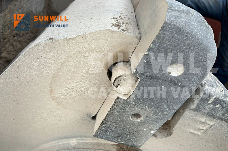
In the high-throughput world of metal recycling, operational uptime is the ultimate measure of success. For a large-scale metal recycling plant in Australia, managing the brutal daily toll on shredding equipment is a constant engineering challenge. SUNWILL understands that shredder efficiency relies on the synergy of the entire wear-part system.

The SUNWILL High-Manganese Advantage

When processing mixed scrap metal, selecting the right material is critical. We prioritize High-Manganese Steel (including Moly-rich variations) for our primary wear parts because of its exceptional work-hardening properties. As the shredder operates, the surface of these components undergoes a continuous hardening transformation upon impact, providing a tough, ductile core that resists fracturing while the surface grows harder to combat abrasive wear.

A Unified Solution for Your Shredder

SUNWILL provides a comprehensive suite of precision-engineered components designed to fit your shredder’s specific metallurgy needs:

  • Premium Hammers: Engineered for maximum impact resistance, our high-manganese steel hammers prevent brittle fracture when encountering un-crushable metal debris.

  • Precision Grates: Our grates are cast from Moly-rich Manganese steel, specifically formulated to handle high-impact environments while maintaining structural integrity.

  • Spacers & Shredder Caps: We offer flexible material options including Mn steel and HB500 alloy steel, ensuring the correct hardness-to-toughness ratio for your specific shredding line.

  • Anvils: Optimized for high-impact loads, our anvils are built to reduce the frequency of maintenance shutdowns and maximize daily throughput

Built for Industry Excellence

Selecting the right wear parts is the most effective way to control operational costs in metal recycling. SUNWILL’s manganese steel parts are designed specifically for the extreme conditions faced by large-scale metal recycling operations, offering a reliable, safe, and cost-effective alternative to brittle alloy compositions.
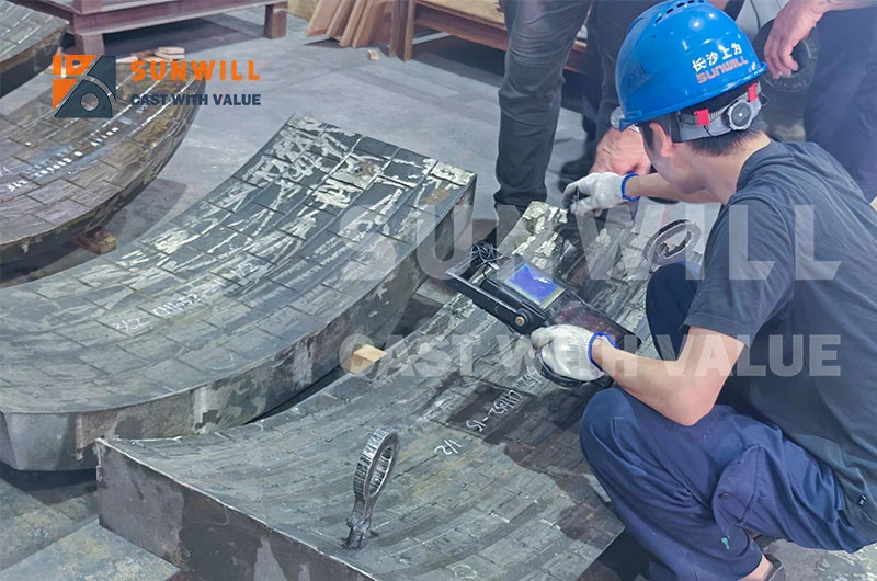
By integrating our specialized Moly-rich grates and precision-fit spacers, we help you reduce your Total Cost of Ownership (TCO). We are proud to partner with industry peers, including our recent project with a large-scale Australian metal recycling plant, to deliver parts that don’t just fit—they perform.
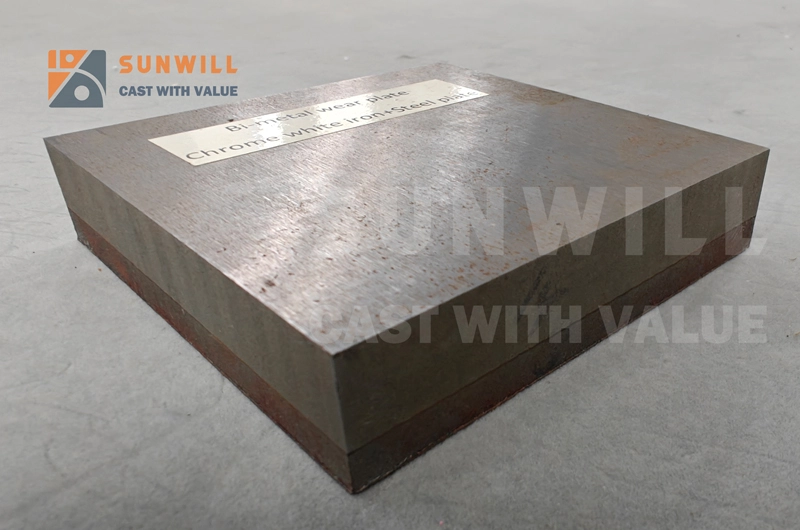
Is your shredding operation ready to boost its impact resistance and reliability? [Link: Click here to contact the SUNWILL engineering team to discuss a customized wear part package for your shredder.]