
Impact Crusher Side Liners: Wear Patterns, Feed Distribution and Replacement
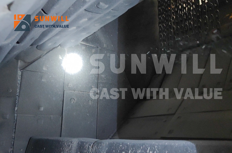
Your worn side liners are a free diagnostic report on your feed system, and most quarries send that report to the scrap bin. Impact crusher side liners do not crush rock. They guard the housing. So when they wear unevenly, the metal is not failing. It is recording something: where your feed lands, how wide it spreads, and how far past its limit your blow bars have travelled.
You already know one side goes faster than the other. What almost nobody does is treat that asymmetry as data rather than an annoying cost line.
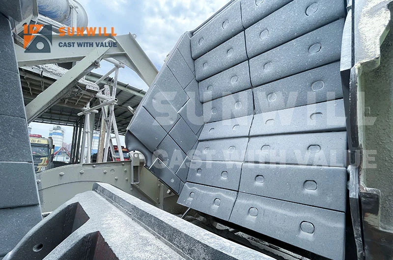
This guide turns impact crusher side liners into a diagnostic instrument: a terminology table that stops you ordering the wrong part, five wear patterns mapped to upstream root causes, a nine point thickness grid, and a replacement rhythm that folds into shutdowns you were taking anyway.
★ Key Takeaways – Impact crusher side liners are housing protection, not crushing tools. Their wear shape is a direct readout of feed distribution, blow bar condition and rotor health. – Five patterns cover almost every case: even full width, one sided gradient, concentrated front, lower through wear, and diagonal sweep. Each points to a different upstream fault. – A nine point thickness grid measured at every shutdown converts guesswork into a wear rate trend, letting you forecast change out two shutdowns ahead. – High wear positions run 2 to 3 blow bar cycles, roughly 800 to 2,000 operating hours in continuous aggregate duty. Low wear positions reach 4 to 6 cycles. – Replace at 25 to 30 percent residual thickness, not on a calendar. Changing liners at every bar change is usually overspending.
What Side Liners Do in a Horizontal Shaft Impactor
Guarding the Housing, Not Crushing the Rock
Blow bars deliver energy. Aprons return it. Impact crusher side liners do neither. They form a sacrificial wall between the chamber and the frame, absorbing the glancing, high velocity rock that sprays sideways off the rotor. A blow bar is consumed by design. A side liner is consumed by accident, and the rate of that accident is set outside the chamber.
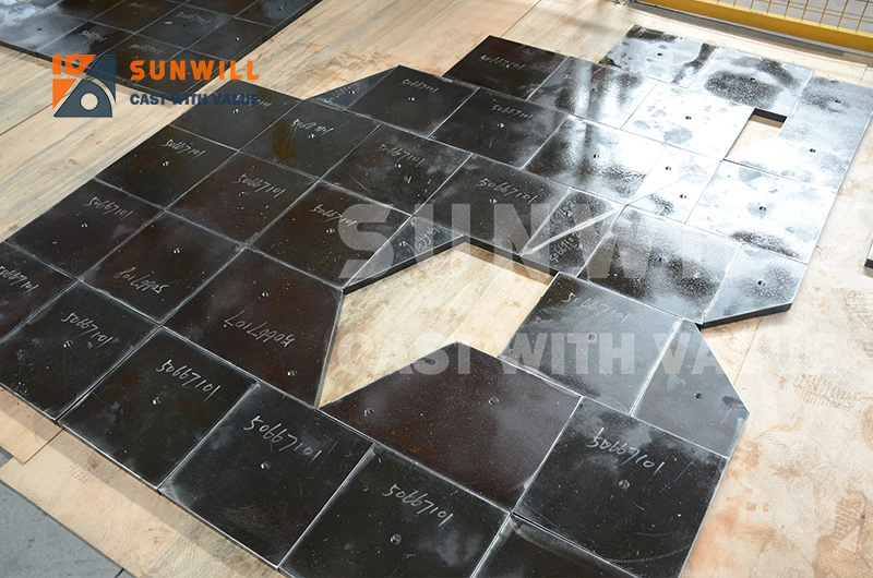
Where They Sit: Feed Inlet, Rotor Zone, Discharge Zone
Most quarry impactors carry side protection in three bands on each wall.
- Feed inlet band. Takes descending rock before rotor contact. Abrasive sliding, usually the slowest of the three.
- Rotor zone band. Severe duty, level with the rotor centreline. Blow bar tip velocity throws material hardest into the wall here.
- Discharge zone band. Sees crushed product and recirculating fines. Moderate wear, but it collects the evidence of material bypassing the crushing zone.
Wear rate differs by a factor of three or more across those bands, so one material and one change interval for the whole wall wastes money.
Side Liner Versus Cheek Plate: Clearing Up the Terminology
This is the most common source of wrong parts arriving on site. The words get swapped freely, but the components are not interchangeable and neither are the machines.
| Machine | Correct part name | Also called on site | What to quote when ordering |
|---|---|---|---|
| Horizontal shaft impactor (HSI) | Side liner, side wear plate | Cheek plate, housing side plate, side guard | Model and serial, band position, bolt pattern, thickness |
| Vertical shaft impactor (VSI) | Cavity wear plate, side wear tile | Side liner | Rotor type, cavity or rock shelf position |
| Jaw crusher | Cheek plate | Side liner, side plate | Frame size, left or right hand, upper or lower |
| Cone crusher | Frame liner, arm guard | Side liner, mantle side plate | Frame size, arm count |
If your machine is a jaw or a cone, the geometry and wear drivers differ enough to need separate treatment, covered in cheek plates and side liners on jaw and cone crushers. Everything below is horizontal shaft impactor territory.
Reading Side Liner Wear as a Diagnostic Instrument
Open the machine, stand back from the wall, and photograph it flat on. The shape of what is missing tells you more than the thickness number does.
Even wear across the full width. A uniform scoured band level with the rotor, fading toward inlet and discharge. Feed is arriving across the full rotor width. Nothing to fix.
One sided gradient. One wall visibly thinner, with a smooth gradient rather than a sharp step. The feed stream is landing off the machine centreline and loading half the rotor. This is the most common finding in quarry impactors and almost never a metallurgical problem.
Concentrated front wear. Heavy loss near the inlet band with a healthy rotor band underneath. Material is entering too far forward and striking the wall before the rotor engages it.
Lower through wear. Loss concentrated low, sometimes breaking through near the discharge. Worn blow bars have lost effective radius, so rock is no longer caught and thrown cleanly. It slumps and grinds along the lower wall. This is a replacement signal for the bars, not the liner.
Diagonal or sweeping pattern. An angled band climbing from one end of the wall to the other. Rotor imbalance or shaft runout is shifting the throw path. Measure before this becomes a bearing problem.
| Wear pattern | Most likely root cause | How to verify | Corrective action |
|---|---|---|---|
| Even full width | Correct feed distribution | Thickness grid within 15 percent across the band | None, maintain current practice |
| One sided gradient | Off centre feed stream | Chalk line conveyor centreline against machine centreline | Shift conveyor or fit a spreader plate |
| Concentrated front | Drop point too far forward | Observe trajectory at reduced feed rate | Move drop point back, reduce drop height |
| Lower through wear | Blow bars past wear limit | Measure bar radius against new dimension | Change bars, then re-check apron gap |
| Diagonal sweep | Rotor imbalance or runout | Dial indicator on shaft, vibration reading | Balance rotor, verify weight matched bar sets |
Industry sources attribute uneven side wear to three dominant causes: off centre feed, rotor imbalance producing eccentric clearance, and apron misalignment concentrating rebound trajectories. In aggregate duty, feed distribution sits well ahead of the other two.
A granite quarry kept replacing the left side liner at twice the rate of the right, and had asked two suppliers for a harder grade. The thickness grid showed a clean gradient, not a hot spot. A chalk line proved the feed conveyor discharge sat about 15 mm left of the machine centreline after a structural repair. A spreader plate and a shim brought both walls within 12 percent of each other over two bar cycles. No material change was needed.
When the pattern does not resolve cleanly, work the symptoms using the full impact crusher wear diagnostic tree rather than changing metal and hoping.
Feed Distribution: The Root Cause Behind Most Side Liner Wear
An impactor rotor is designed to be loaded evenly across its length. Concentrate the stream into the middle third and you overload three blow bar segments, under use the rest, and sharply increase the sideways component of the throw. Spread the same tonnage across the full width and impact crusher side liners last longer with no change in material or tonnage.
A belt discharging as a narrow stream is the default on most plants, because nobody specified otherwise. That stream is usually segregated too, with coarse rock on one side after the last transfer, giving you both an off centre load and a size gradient across the rotor.
The cheapest fixes are geometric: a spreader plate in the feed box, a shortened drop height, a feeder run wider and slower rather than narrow and fast, and correctly profiled feed chute liners that direct the stream instead of merely surviving it. If the stockpile is segregated, the asymmetry arrives before the belt does.
Photograph your side liner wall flat on, with a tape measure in frame for scale, and send it over. Our engineers will read the pattern and tell you what to check upstream before you buy anything. Send us a wear photo
Wear Mapping: Turning Guesswork Into a Trend Line
A Nine Point Thickness Grid
Stop recording one number. Record nine, in the same places, every time.
Divide each wall into a three by three grid. Columns run front to back: A at the feed inlet, B on the rotor centreline, C at the discharge. Rows run top to bottom: 1 upper, 2 middle, 3 lower. That gives nine fixed points, A1 through C3, per wall and eighteen per machine.
Mark the points permanently with a centre punch or paint stencil so every technician measures the same spots. Record thickness, hours since the last reading, and tonnes processed.
Ultrasonic Gauging Without Removing the Liner
An ultrasonic gauge reads through the plate from the accessible side, so you get numbers during a routine inspection stop rather than a strip down. Clean the surface, use couplant, take three readings per point and keep the median. Inspection every 50 to 100 operating hours is the commonly cited rhythm for impactor liners. For gauge selection and the laser scanning alternative, see liner wear monitoring methods.
Building the Rate Trend
Two readings give a rate in millimetres per hundred hours. Three or more give a trend, which lets you order on normal lead time instead of an emergency one. Divide remaining thickness above your limit by the current rate and you have a change out date.
Want the nine point grid as a printable log sheet with the rate calculation built in? Ask for the side liner thickness template. Request the template
Material Options for Quarry Side Liners
Position, not preference, drives the grade. Here is how SUNWILL matches metal to duty on impact crusher side liners.
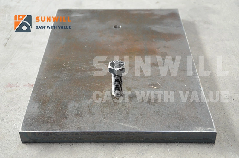
- Alloy steel for impact zones. Where tramp metal risk is real or feed is blocky, toughness beats hardness. The safe default for feed inlet bands.
- High chrome white iron for abrasion positions. For high silica feed in the rotor and discharge bands where contact is glancing rather than blunt. Unforgiving of direct impact, so position matters.
- Bimetallic for mixed duty. A hard working face bonded to a tough backing, for walls seeing blunt impact at the inlet and severe abrasion at the rotor line.
The most cost effective specification usually mixes grades within one machine. Our quarry wear parts selection framework covers the rock property inputs, and the same logic drives blow bar grades for hard rock quarries.
Industry Grades We Do Not Cast
Being straight about scope saves everybody time.
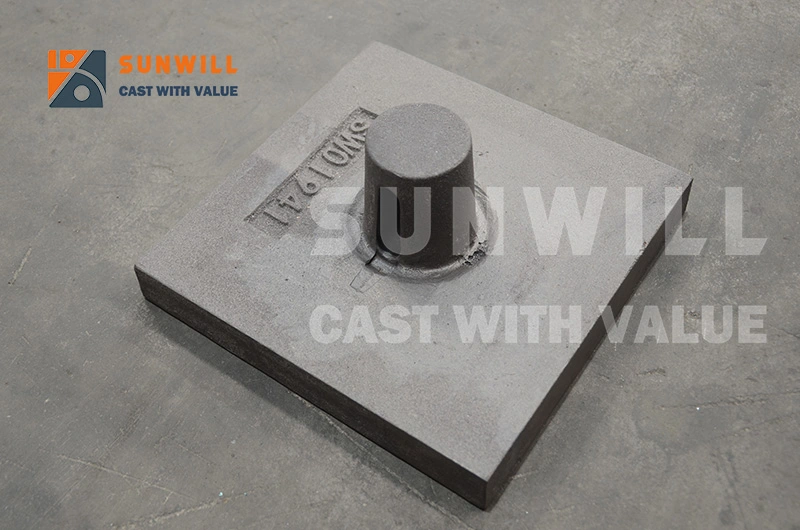
- Standard Hadfield manganese steel (Mn13, Mn14Cr2, Mn18Cr2) is widely used for side liners across the industry. Published figures such as 200 to 220 HB for Mn14Cr2 and 200 to 240 HB for Mn18Cr2 are cited here as objective industry reference only. SUNWILL does not produce standard Hadfield manganese steel castings.
- TiC reinforced manganese steel is available from us as a separate product line, not standard Hadfield casting, with a different reinforcement mechanism and different application rules.
- Ni-Hard (ASTM A532) is not a stock item for us. Where the duty calls for it, we specify and source the correct Type 1, Type 2 or Type 4 grade as part of a complete wear solution.
- Chromium carbide overlay (CCO) and tungsten carbide composites appear here for solution comparison only. They are not manufactured by SUNWILL.
Replacement Intervals and Synchronising With Blow Bar Changes
Side liners take glancing contact, not direct impact, so they outlast the bars by a wide margin. High wear positions run 2 to 3 blow bar cycles, around 800 to 2,000 hours of continuous aggregate production. Low wear positions reach 4 to 6 cycles. For comparison, jaw crusher cheek plates commonly last 2 to 4 times a set of jaw dies.
Two residual thickness thresholds are widely used: replace at 25 to 30 percent of original thickness remaining, or replace once 30 to 40 percent has been lost. Set the tighter limit where a breakthrough would gouge the frame, and the looser one at low consequence positions.
You are already opening the machine for bars. Measure impact crusher side liners at every bar change, then schedule the swap into a bar change window when the forecast says the liner will not survive two more cycles. One isolation, one lockout, one crew mobilisation. Plan the sequence alongside the synchronising side liner and blow bar changes procedure, verify fastener condition against liner bolt retention practice, and re-confirm your apron gap setting before returning to production.
A limestone operation treated side liners as an unplanned job, stopping the plant whenever a wall got thin. After adopting the nine point grid, they found the rotor band consistently ran out at about 2.5 bar cycles. They moved that band to every third bar change and left the inlet and discharge bands on condition. Over twelve months that meant three fewer unplanned stops, with no increase in liner spend.
Send your machine model, serial number and the band positions you need, and we will quote fitment matched castings with inspection records. ISO 9001:2015 foundry, and we CAST WITH VALUE. Request a quotation
OEM Fitment Notes for Quarry Impactors
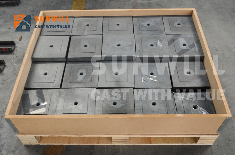
Side liners are not universal, and a photograph alone is rarely enough. Send the machine make, model and serial number, the band position, overall dimensions and thickness, the bolt or wedge pattern with hole centres, and a photo of the mounting face with the old liner removed. Where an OEM part number is stamped, include it. That normally confirms fitment without a site visit.
Frequently Asked Questions
Why is one side liner wearing faster than the other?
Almost always because the feed stream lands off the machine centreline, loading one half of the rotor and throwing more material into that wall. Chalk the conveyor discharge centreline against the machine centreline before considering harder metal. The other credible causes are rotor imbalance or shaft runout, and apron misalignment concentrating rebound on one side. A thickness grid separates them: a smooth gradient means feed, an angled band means rotor.
What is the difference between a side liner and a cheek plate?
They protect the same thing, the crusher housing sidewall, but on different machines with different geometry. Side liner is correct for sidewall protection in a horizontal shaft impactor, supplied in bands at the feed inlet, rotor zone and discharge. Cheek plate is correct on a jaw crusher, where flat plates protect the frame sides alongside the jaw dies. The terms get used interchangeably on site, which causes wrong parts to be ordered. Always quote machine type, model and serial number.
How often should impact crusher side liners be replaced?
Run them on condition, not on a calendar. In continuous aggregate duty, high wear positions such as the rotor band last 2 to 3 blow bar cycles, roughly 800 to 2,000 operating hours, while inlet and discharge positions reach 4 to 6 cycles. The practical trigger is residual thickness: replace at 25 to 30 percent of original thickness remaining, or once 30 to 40 percent has been lost. Measuring at every bar change lets you forecast the change out.
Can I measure side liner thickness without removing it?
Yes. An ultrasonic thickness gauge reads through the plate from the accessible side, so you can take readings during a normal inspection stop. Clean the point, apply couplant, take three readings and keep the median. Use a fixed nine point grid, three columns from inlet to discharge and three rows from top to bottom, marked permanently so every technician measures the same spots. Recording hours and tonnes alongside each reading turns numbers into a usable wear rate.
Do I need to change side liners every time I change blow bars?
No, and doing so is usually overspending. Side liners typically survive two to six blow bar cycles depending on position, so a blanket change at every bar change discards serviceable metal. Inspect and measure at every bar change, then schedule the liner swap into a bar change window only when the wear rate trend says the liner will not survive two more cycles. That keeps the work inside a shutdown you were already taking.
What material should quarry side liners be?
Match the grade to the band, not to the machine. Heat treated alloy steel suits feed inlet positions and any duty with tramp metal risk, because toughness matters more than hardness there. High chrome white iron suits rotor and discharge bands in high silica abrasive feed where contact is glancing. Ceramic composite gives the biggest step change in severe abrasion. Note that SUNWILL does not produce standard Hadfield manganese steel, and our TiC reinforced manganese is a separate product line, not standard Hadfield casting.
Conclusion: Your Side Liners Already Wrote the Report
The metal on your chamber walls has been recording your feed system for months. Even wear means you are feeding the full rotor width. A one sided gradient means the stream is off centre. Front loading means the drop point is too far forward. Low through wear means your bars are finished. A diagonal sweep means check the rotor before it becomes a bearing failure.
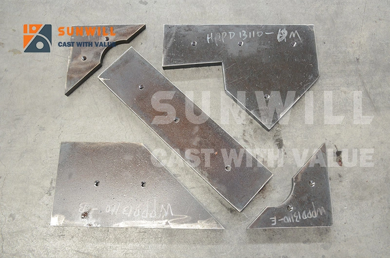
Start with three things. Mark a nine point grid on both walls. Photograph each wall flat on at the next shutdown. Chalk your conveyor centreline against the machine centreline and see whether they agree.
Do that, and impact crusher side liners stop being an unpredictable cost line and become the cheapest diagnostic instrument in your plant.
When the readings say it is time, we cast alloy steel, high chrome white iron, ceramic composite and bimetallic liners to your machine and your duty, with ISO 9001:2015 inspection records in the box. Send us your model, serial and wear photos for a fitment matched quotation
Standards and Authoritative References
- ASTM A532 / A532M, Abrasion-Resistant Cast Irons – the issuing body for the Ni-Hard Type 1/2/4 designations named in this article.